Analytical instrumentation
There are three types of combustion methods in which carbon dioxide can be captured: post-combustion, pre-combustion, and oxyfuel technology.
Within each of these methods of carbon dioxide capture, post-combustion is the easiest to retrofit into refineries.
With the post-combustion methods, ionic liquids, membrane technology, cryogenic separation and adsorption were quantitatively analyzed to determine which is the most energy efficient.
When this was conducted, it was found that ionic liquids had the least amount of energy consumption when compared to methods which had a similar capture rate and purity percentage.
There are other non-combustion methods of carbon capture as well. A few of these methods include direct air capture, and industrial process capture.
The economic issues plagued by carbon capture and storage are also explained and possible solutions such as hybrid capture technologies and hybrid transportation methods are elaborated on.
More research is needed into experimental results to confirm if hybrid transportation systems/capture systems can improve the economic viability of the carbon capture utilization and storage (CCUS) process.
Carbon capture and storage (CCS) is a method in which carbon dioxide is captured via chemical and physical processes to be stored underground [1].
There are three types of methods of capturing carbon dioxide: post-combustion, pre-combustion, and oxy-fuel technology [2].
In the post combustion type of CCS, carbon dioxide is separated from flue gas (which is the mix of byproduct gases of reactions in power plants or refineries) through the usage of a chemical solvent.
This solvent is what binds to carbon dioxide, after which, the remaining air is sent into the atmosphere. The most common absorbent involved is monoethanolamine [3].
The carbon dioxide captured from the process is stored underground or used in industry [4].
An important disadvantage of this method is that there is a low concentration of CO2 present in the flue gas so it can be an inefficient process as a significant amount of energy can be needed to complete the process [5].
The latter type of combustion process is called pre-combustion. In this type, a fuel is converted into a gaseous mixture of hydrogen and carbon monoxide before being burned.
The carbon monoxide is then reacted with steam to make more hydrogen and converts the carbon monoxide to carbon dioxide, which is separated away from the remaining hydrogen, which is used as fuel.
The third form of capture is oxy-fuel technology. This involves burning fuel with near-pure oxygen, producing CO2 and steam [2].
There are also some methods of carbon capture which are from non-combustion sources. One type of carbon capture is Direct Air Capture (DAC) and another type is the industrial process capture.
These methods are used less often than post-combustion and so they will be explained and evaluated in more detail in the paper [6].
After carbon dioxide is captured, it is then injected into deep geological formations such as saline aquifers, depleted oil or gas reservoirs, or active reservoirs for EOR [6].
There are four methods in which carbon dioxide can be sequestered: structural trapping, residual trapping, solubility and mineral trapping [7].
Structural trapping uses impermeable rock above carbon dioxide to prevent escaping long-term [7].
A major disadvantage of this method is that caprock and possible well failure may allow the carbon dioxide to escape [7].
As a result, the other methods are more commonly used [7]. Residual trapping is where CO2 is retained through capillary forces within the reservoir itself [7].
In solubility trapping, the carbon dioxide dissolves in saltwater present in the rock [7]. Because the saltwater containing carbon dioxide is denser than the other fluids, the former liquid will sink to the bottom, securing the carbon dioxide [7].
In mineral trapping, carbon dioxide forms carbonic acid when dissolved in water which can react with minerals to form carbonate minerals [7]. The full process of CCUS is summarized in Figure 1 in a flow chart.
While CCS has shown promise, there are various disadvantages. An important disadvantage is that it can be economically unviable as high energy costs are associated with the project, which can cancel out the carbon dioxide which was captured from the air [1].
However, there is a newer process which can be more economically viable while being more sustainable for the environment - Carbon Capture Utilization and Storage (CCUS).
In this novel method, carbon dioxide can not only be stored underground but can also be used for other chemical processes as well.
This can include manufacturing polyols, methanol, and more [8] [9]. In this paper, the technologies in both post-combustion and pre-combustion capture method types will be covered, including their advantages, disadvantages, and comparisons to other technologies.
Also, the economic issue behind the energy costs found will also be discussed as well along with some potential solutions.
Figure 1: This flowchart shows the full carbon capture and utilization and storage process which will be discussed in this literature review.
As said before, there are three types of carbon capture which include post-combustion capture, pre-combustion capture, and oxy-fuel technology [3].
In the pre-combustion process, carbon dioxide undergoes compression and liquefaction for storage/transport and has a lower overall energy requirement than for post-combustion capture.
The purified hydrogen can be used in fuel cells and as a building block for other chemical compounds such as high-octane gasoline [3].
The process can be cheaper than the post-combustion and oxyfuel combustion routes by 38-45% and 21-24% respectively [10].
However, energy is still needed for the chemical reformation process, and further purification stages when oil and coal are used to eliminate impurities which include sulfur-containing compounds [3].
Another issue was that the water-gas-shift reaction (WGSR), the reaction in which carbon monoxide is converted into hydrogen fuel and carbon dioxide, was found to be responsible for 44% of total efficiency loss within the full CCUS process.
However, this issue has been mitigated with atomic dispersed metal catalysts which have proven to convert more CO than with previous copper catalysts involved with the reaction.
Because these catalysts have virtually all the active metal atoms on the surface, this leads to nearly 100% efficiency [11].
This has led to many catalysts involved with the carbon dioxide pre-combustion capture process having had up to 100% full CO conversion [11].
However, these catalysts are difficult to prepare and metal loading of the catalysts is low.
More research is needed in providing corroborative evidence that these catalysts can be prepared more efficiently, which can cut costs, further improving the economic viability of the process.
As shown, there are numerous research projects occurring on how to make pre-combustion more viable and easier for application in refineries and power plants.
On the other hand, the post-combustion method can also be an economically viable option for capture as well.
It has a lower amount of energy needed, can be easier to implement in commercial spaces such as in refineries and scale up in power plants [12].
Because monoethanolamine (MEA) is the most widely used amine solvent, though many others exist (DEA, MDEA, piperazine), and high regeneration energy and corrosivity make it expensive to operate, and some projects have been shut down as a result [13].
In the oxyfuel combustion process, a carbon-based fuel is combusted in circulated flue gas and pure oxygen.
This process has been shown to be promising because of a low-efficiency penalty of 4%, which is half or one-third of post combustion [13].
In addition to that, there are lower emissions present and it is simpler [14].
However, oxygen is expensive and cryogenic distillation is the dominant technology for producing oxygen at large scale, though pressure swing adsorption (PSA) can also produce oxygen industrially at lower purity [15].
To mitigate the issue, oxygen-transport membranes are used [10] [16]. Carbo et.al found that these membranes can save 19-50% more than post-combustion technology [17].
However, the cycle efficiency drops 9-13% when carbon dioxide purification and compression units are involved in the combustion system as they further complicate a simple system [3].
In this report, the focus will be more on post-combustion capture techniques as they are more prevalent within the research field and are easier to retrofit into refineries and can be found to be generally more inexpensive to run than oxy-fuel combustion routes for reasons described above [18].
There are four kinds of post-combustion carbon capture: general absorption, membrane technology, cryogenic separation, and adsorption.
One type of absorption method involves ionic liquids. Ionic liquids can be used to absorb carbon dioxide [1].
It is an environmentally friendly and stable process. However, much of the solvent can be lost and equipment can corrode because of the process [1].
In membrane technology, polymer membranes can be used to separate carbon dioxide from the mainstream [19].
The efficiency of the process is high because of the ease in installation. However, a major caveat in the process is that it is very intensive in terms of energy usage in cooling, as these fuels may get extremely hot which may affect the internal hardware [1] [19]. In cryogenic separation, a gas mixture is refrigerated, and condensation occurs to separate carbon dioxide in a solid form [1].
The main advantage involved with this process is that these carbon dioxide blocks can be transported easier and can be used when carbon dioxide concentrations are high [20].
However, it can be expensive to conduct the process, provide the energy required for refrigeration, and pre-removal of carbon dioxide is needed to ensure maximum efficiency [20].
Adsorption occurs when a surface is used to make carbon dioxide adhere to it through various chemical attractions and can occur in the external surface [21].
All four of these types of capture and their relative energy consumptions, carbon dioxide purities which are experimentally found or assumed are in Table 1 and explained in the next section.
There are various metrics of comparing the processes involved in carbon capture, however, the metric which can be considered the most vital for a refinery is the energy consumption of each process.
Literature reviews and experiments are present that provide these figures.
For example, in (Vadillo et.al’s experimentation/literature review), in Table 1, it can be seen that the range of energy consumption modeled and simulated for the CO2 desorption process developed by a coupled membrane vacuum regeneration technology(MVR), in which a vacuum is used on a side of a membrane to release carbon dioxide [22]. for the imidazolium based ionic liquid at 289-313 K at 0.04-0.88 bar pressure is 0.34 MJ/kgCO2 while the other ionic liquid studies in Vadillo’s literature review/modeling/simulation paper had a range from 0.25-1.6 MJ/kg CO2 used.
It can also be seen that in Aneesh et.al’s literature review in Table 1, in various methods of conducting cryogenic separation, the energy consumption can range from 0.63 to 1.8 GJ/t of CO2, which is higher than the previous range [23].
Also, for table 1, we can also see that for the membrane-based direct air capture system(m-DAC) conducted by Niesporek et.al was conducted from a combined cycle(cc) system which is where a three-pressure gas-steam system fueled by methane was used to generate electricity which is used to run the membrane separation process by increasing the carbon dioxide concentration in the feed system [24].
All of the this was modelled by the Aspen processing system using various assumptions which included Fick’s first law, which is defined as the diffusion flux, the amount of substance per unit are per unit time being equal to the negative of the concentration gradient, defined as the partial derivative of concentration with respect to three dimensions, times the diffusion coefficient.
The concentration gradient specifically is affected by the change in concentration, membrane selectivity, permanence of gas components, the recovery rate, etc.
These equations were all affected by the permeate mass flow rate, feed mass flow rate, mass fractions of carbon dioxide in the permeate and in the feed.
The energy calculation, which is the most important metric needed to compare the previous methods discussed, was calculated using the vacuum pump power requirement and initial fan power requirement.
The mechanical and isentropic efficiency of the pumps were set to be at 99 and 90% respectively. Atmospheric air is transferred to the first membrane at an overpressure, initiating diffusion.
A vacuum pump is used to maintain the pressure difference while reducing energy consumption for the general process and is used in a four-stage vacuum pumping system.
In each of these pumping stages, the energy intensity of the capture process was measured in GJ/tCO2, and is in Table 1, with the lowest in the pumping stages being at 2.22 GJ/tCO2.
When Pirngruber et.al conducted a study on adsorption as a post-capture method, it was found that the minimum amount of energy needed to run the process (energy demand) of the full process ranged from 2.7-2.9 MJ/kg or GJ/T of CO2 [25].
The general carbon capture of this method is agreed to be around 98%, and the purity of carbon capture at the plant being at least 98%, regardless of conditions [26].
This is significantly higher than the ionic liquids involved in absorption or with the membrane-based capture involved.
While energy consumption is a critical metric for application of carbon capture processes in refineries, the carbon dioxide recovery percentage and purity are also critical.
As shown in table 1, the post-capture methods involving ionic liquids and membrane technology have had the most consistent and highest carbon dioxide recovery which may be attributed to the properties of the ionic liquids reducing the amount of systematic error which may occur during the process.
This can be because of the cation/anion of the molecules in the ionic liquids allowing for more carbon dioxide to be captured [27].
As shown in Table 1, the ionic liquids from Vadillo et.al’s research paper have had the least number of expenditures in terms of energy consumption.
However, there are some more disadvantages to ionic liquids which were not discussed previously.
There is a substantial steam input requirement for regeneration for amine-based processes (for ionic liquids) [1].
While new materials have been found which can improve absorption further, they may be unstable and may cause equipment corrosion.
These disadvantages may cancel out the economic benefit of having a lower energy cost in the capture process.
Another consideration to keep in mind is that some of this data is acquired from doing various machine learning models to retrieve these statistics.
These models require various assumptions to run which are explained in the caption. Because of these factors, the models may not accurately reflect the experimental data for that specific ionic liquid.
While there are ionic liquids which have been found to be economically viable experimentally, more consolidated experimental research is needed to determine the most cost-effective method of post-combustion capture.
Caption for Table 1: In this table, the four methods of post-combustion capture are compared in terms of energy consumption, purity in carbon dioxide, and the capture rate.
Energy Consumption (EC) is shown to be the lowest when the ionic liquid solvent is used.
Some statistics (secondary sources) were found in literature reviews (primary sources) For papers found in Vadillo et.al, it is assumed that there is only two streams present in the liquid stream(carbon dioxide and the ionic liquid itself), and in Niesporek, it is assumed to be that throughout the process, so remaining rows are not filled in.
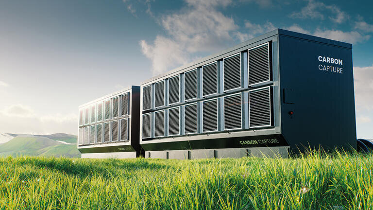
As said previously, there are other types of non-combustion related methodologies in which carbon dioxide is captured from the air.
Two of the types of methods discussed include direct air capture (DAC) and the industrial process capture methodologies.
In direct air capture, carbon dioxide is extracted directly from the air in two methods: liquid solvents and solid sorbents [28].
Air passes through chemicals that remove the carbon dioxide and heat, and a vacuum is used to remove carbon dioxide from the air.
Some examples of these chemicals would include sodium hydroxide and potassium hydroxide [29].
The treated air is then returned into the atmosphere. In sorbent-based direct air capture systems, physical filters chemically bind to carbon dioxide.
When the filters are placed under a vacuum and/or heated, carbon dioxide trapped in the filters are released [28].
Direct air capture focuses on the removal of carbon dioxide from the air itself which is not what combustion-based capture methods were meant to do. While the latter type is to be used to reduce carbon emissions, the former is meant to be used to directly remove carbon dioxide from the atmosphere which can be tracked in real-time, making it easier to model carbon footprint reduction [30].
The main downside with this type of combustion capture is the cost. Because only 0.04% of the atmosphere has carbon dioxide, it can be an extremely economically unviable process to directly capture it from the air [31].
As a result, it is used less often in power plants and in industrial processes than combustion-based capture which has been the bulk of this review [32].
The second method is involving industry capture processes. Some methods involved in this type of capture include calcium looping in cement production, ammonia synthesis and natural gas sweetening.
In cement calcination, calcium oxide (lime) is mixed with carbon dioxide in a mixed reaction to produce calcium carbonate which is transferred to the calciner in which the carbonate is decomposed into lime and carbon dioxide again [33].
This lime is transferred back into the carbonator to generate more calcium carbonate.
The carbon dioxide is then sent to a compression unit to be sequestered (more on that below).
This process is repeated to increase the purity of the carbon dioxide in the chemical process system.
In the ammonia synthesis method, green ammonia can be made through hydrogen generated with electrolysis, and nitrogen extracted from the atmosphere.
These two elements are then combined with the use of the Haber-Bosch process, where they are combined at high heat and pressure in the presence of a catalyst to form ammonia, with the key difference being in where the hydrogen and nitrogen are sourced [34].
This ammonia can be used as a solvent in which carbon capture can occur and can also save in emissions when making ammonia as hydrogen and nitrogen are sourced from renewable resources [35].
In the natural gas sweetening method, hydrogen sulfide and carbon dioxide are removed from natural gas to sweeten the gas.
This is to prevent corrosion in gas pipelines and toxicity in humans [36].
The sour gas sweetening can occur through membrane technology or through absorption with amine scrubbers [36][37].
Membrane technology is used to separate water vapor, hydrogen sulfide and carbon dioxide. In conclusion, there are other methods than combustion-based capture methods which include DAC, natural gas sweetening, calcium looping and ammonia synthesis.
However, these methods have been found to be less economically viable than combustion-based capture, which is one of the main focal points of this review.
After carbon dioxide is captured, it can be transported in many ways.
In truck transport, carbon dioxide is loaded through the dry ice method into the containers [1].
The main research focus now is finding how to reduce cryogenic processing costs and improve integration of pipelines and trucks [1].
Another method of transport is through pipelines [1]. These are the most preferred transportation methods, in which carbon dioxide is supercritical [1].
However, these pipelines can pose safety risks to those involved in the construction and usage of them and travel flexibility is not feasible [1].
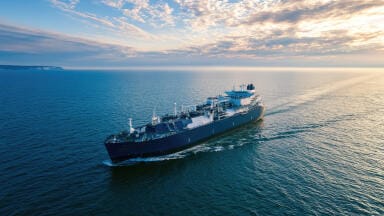
Another option for the transportation of carbon
dioxide is through ships. The carbon dioxide is liquefied and kept at a low temperature and high pressure.
This allows the carbon dioxide to be more flexible in phases than in the pipeline transportation method.
Some disadvantages of involving ship transportation are that the liquefaction and gasification of carbon dioxide can be technically taxing, and managing complex regulations and port constraints may complicate operations, further increasing the cost of the process [1].
Enhanced oil recovery (EOR) is one application in which CO2 is injected into active oil reservoirs to improve crude oil recovery, distinct from geological sequestration where CO2 is injected for long-term storage.
There are three displacement regimes in CO2-EOR: immiscible displacement, near-miscible displacement, and miscible displacement.
This is affected by the formation pressure, which is the fluid pressure within the pore spaces of the reservoir [38].
If the formation pressure is less than the minimum pressure between carbon dioxide particles and the formation oil, then immiscible displacement is occurring.
Only some of the carbon dioxide can interact with the oil and lower recovery is possible. If the formation pressure is similar or equal to the minimum pressure, there is a higher oil recovery.
The carbon dioxide and crude oil form a dissolved combined phase if the formation pressure is higher and the carbon dioxide separates from the crude oil.
While storage may be a simpler method of finishing the carbon capture process, utilization has been found to be more economically viable than simple storage as the costs of conducting the storage process are difficult to recover [1].
In Khan et.al, methane is used to make a low-carbon fuel called blue hydrogen [9].
This blue hydrogen can be used to make hydrogen to power a distillation plant which can be used to create more chemical products such as a light straight run gasoline (LSRG), naphtha.
LSRGs are used in the blending process for gasoline while naphtha is used in the chemical processes of making plastics [39] [40].
The main goal of Khan et.al is to find economically viable low-carbon fuels such as blue hydrogen are.
Economic and life-cycle assessments were all completed through process simulations [9]. There were four cases studied. In one case, a crude oil distillation unit would use blue hydrogen.
In the second case, the unit would use green ammonia, which is produced through combining hydrogen from water electrolysis and nitrogen from the atmosphere with the Haber process, which would have a lower combustion speed and narrower flammability range than hydrogen [35]. The third case is that blue ammonia would be fuel for the unit [9].
In the fourth case, the utilization of captured carbon dioxide would be used to produce methanol and urea [9].
The goal in this case is to make a carbon dioxide utilization pathway related to the capture process.
In the methanol process, an excess amount of blue hydrogen is used as a fuel in addition to producing methanol [9].
This involves a bigger steam reforming surface than in Case 1 to produce more flue gas which increases CO2 capture [9].
The remaining CO2 from the methanol process is then used to make urea with green ammonia.
There are various assumptions made within the model, however. One is that the mixture input into the CDU is a Saudi light crude assay [9].
An efficiency factor of 70% is placed in the NH3 combustion modeling, and about 90% CO2 recovery rate is assumed to be the first case [9].
The process-based simulations found that blue hydrogen (in the first case) had the highest emission reduction at the lowest cost ($101/ton of CO2) [9].
While the fourth use case was the most complicated, it was found to have a 31% higher carbon avoidance cost than in cases 1.
Carbon dioxide sales revenue is shown to be critical for viability through Monte Carlo analysis [9].
But a downside of this is that these are economic simulations with assumptions regarding specific kinds of crude oil mixtures and recovery rates [9].
In a nonideal experiment, stream kinds, recovery rates and efficiency factors are all variables [9].
While there is machine learning research into the utilization of carbon dioxide, more experimental/economic research is needed in the utilization portion of the process [9].
While naphtha, LSRGs, and urea are some products of the utilization process, carbon dioxide itself can be utilized in a variety of use cases: urea yield boosting feedstock, EOR solvents, and heat transfer fluid in refrigeration and in supercritical power systems [41].
While this process is promising, as the purity of carbon dioxide is generally high within these processes and the capture rate of carbon dioxide is also high, there are various economic issues which are preventing the goal of net-zero carbon dioxide emissions from being achieved. The main issue is that many of these technologies have high energy requirements and high capital and operating costs [41] [42][34].
In fact, ionic liquids, which were the solvents which had the least amount of energy consumption used in the studies reviewed previously, are higher in cost than traditional solvents.
The capture process itself accounts for 50% of the total costs of the process and can cost up to 90% of the total costs if compression is involved [44]. Within post-combustion capture, air pollutants present in the flue gases need to be removed to an extremely low level before the capture process begins [45].
This is a major reason as to why capture processes can be costly within the methods discussed.
There are some reports in which absorption enhanced water gas shift reactions can reduce the specific primary energy consumption from 2.9 MJ/kgCO2 to 2.5 MJ/kgCO2 [46].
For oxyfuel, the cryogenic air separation process involves a separate air separation unit which makes the oxygen for combustion.
This can be expensive and can be estimated to consume 15% of the power plant’s output and 26% of equipment costs [47].
The study from Gazzani et.al and the encyclopedia page show that hybrid capture systems can improve the economic viability of the CCUS system [46][47].
Because individual systems can be complex and expensive on their own, which can negatively impact the economic viability of CCUS, hybrid capture processes can be recommended to reduce capture costs.
However, there are conflicting reports which show the opposite. In the review conducted by Karayil et.al, it can be found that the cost of capturing a ton of carbon dioxide if using an absorption method can range from $40-100 USD [48].
Using the same review, it can also be seen that the membrane also has a capture cost between $15-55/tCO2.
The articles cited range from 2012 to 2020, which means that those prices are higher when adjusted for inflation [48][49], [50][51][52].
However, an amine-based carbon dioxide capture method involving membrane contactors has been experimentally proven to have a capture cost of $36/tCO2 which is significantly lower than the absorption range and within the range of costs for the membrane-based separation process.
This shows that while preliminary research shows that hybrid methods of carbon capture can improve the economic viability of the CCUS process, more analytics is needed to confirm this through implementation in the retrofitting of the CCUS process.
There is another possible solution: having a hybrid transportation system. While transportation is not the only cost of travel, a hybrid-model of transportation could make the process more economically viable. An example of a case study involving hybrid systems is in Turkey.
In Turkey, there were four scenarios modelled out using 64 facilities in Turkey which are cement plants, iron and steel mills and refineries using single-objective mixed-integer linear programming, which is a mathematical optimization technique [53].
The model has spatial features which were used to help the model “envision” the locations of the 64 facilities using a grid which would turn Turkey from an uneven shape representation to being represented with decently sized squares [53].
In the modelling, there are different types of capturing, transportation, storage and recovery/utilization involved with each scenario [53]. Irrespective of transportation, the type of capture depends on the kind of plant involved.
In refineries and steel mills, monoethanolamine (MEA) based post-combustion capture technology is selected for its high energy efficiency (as shown in the quantitative analysis section), low costs and ease in application and is conducted in three stages [53].
Cement plants used oxy-fuel combustion in their capture process [53]. In the base case, CCS is conducted with only pipelines used and about eight storage sites into account [53].
To calculate ship distances, the law of cosines based on geographical coordinates is utilized [53].
The pipeline transport is assumed to have a range of flow rates and costs related to the pipeline construction are affected by various factors such as pre-existing pipelines, rivers, lakes, etc [53].
These factors were all found in Yeates et.al 2024, and Kim et.al 2018 [53][54][55]. Ship-based transport is modelled similarly to trains as ship transport is affected by distance and CO2 ship transportation is assumed to be at low pressure.
The transportation involves processes similar to railway transportation and the transport capacity with unit cost per ship is considered negligible for long distances [53].
For utilization, the demand of methanol, the selling price of methanol, the cost of synthesis, the mass ratio of CO2 consumption and electricity consumption of methanol production plant are all assumed to be constant [53].
There are four scenarios modelled with these conditions in mind [53]. In the base case, CCS is conducted with only pipelines used and about eight storage sites into account [53].
The first scenario is in which local transportation like railways are used to minimize cost in CCS and all transportation is within Turkey [53].
The second scenario is in which carbon dioxide is exported to storage sites outside of Turkey through ships [53].
In the third scenario, the pipelines and ships are used to transport CO2 to offshore sites but those are the only sequestration sites considered (no sites in Turkey) [53].
The final case is in which CCUS is conducted in which synthetic methanol production is the utilization of CO2 [53].
Each scenario was also run with carbon reduction targets ranging from 10-90% [53].
The total cost was defined to be the sum of the total capture cost, transportation cost, storage cost, and utilization cost minus the revenue from the methanol production [53].
When comparing the 90% carbon reduction targets, the base case had a total cost of 119.4 euros/ton of CO2 captured, the first case had a total cost of 110.2, the second had 120.3, and the third had 131.1 [53].
The results show that the best efficient solution is in the scenario in which rail and pipelines are combined (scenario 1).
A study done previously by Kumcu et.al involved using the same MILP framework to minimize costs for a CCS network [56].
While the total cost of capture for both studies is similar in all cases (carbon reductions), the main difference is that in the latter, hybrid transportation systems and carbon dioxide conversion and utilization is involved.
Figure 2 compares the previous study to the most recent study by the same authors.
Because these costs are still similar, this shows how the economic viability of the process can be improved with the usage of hybrid transportation systems and in the utilization of the byproducts of the process such as methanol.
This has shown how hybrid transportation technologies, alternative carbon dioxide utilization, and access to low-cost renewable electricity are all clear variables which affect the cost of the process and the presence of which can lower the cost of the process [43].
One important consideration for this study is the fact that the demand of methanol and the price of methanol is kept constant [43].
This is crucial, as the model cannot model uncertainty in prices of methanol. A future research focus in the economics of CCUS could be in modeling the uncertainty in the prices of methanol and utilizing it to determine what factors in the capture process could be reduced to keep the process profitable/economically viable.
Figure 2: In this figure, it is shown that even with additional costs discussed previously, the hybrid transportation method is still similarly economically viable, which shows that hybrid transportation methods can help with improving economic viability. For clarity, the nonhybrid costs are related to the 2025 study while the base, S1, S2,S3, and S4 scenarios are related to the 2026 case study.
In this paper, the process of capturing carbon dioxide, the methods in which capture is conducted, the methods in which carbon dioxide is stored and utilized, economic issues with the process and possible solutions to these economic issues are discussed.
When comparing the various methods of post-combustion capture, a type of carbon capture, it was found that the ionic liquids have a lower overall energy consumption figure when compared to other methods.
However, ionic liquids have some risks which include equipment corrosion and solvent loss.
The main economic issue within the process is that the capture process makes up to 50-90% of the total cost.
These processes can be hybridized with other capturing methods which have shown themselves to be more economically viable.
However, more research is needed to confirm this possibility.
In addition to this, hybrid transportation models and utilization of carbon dioxide have also improved the economic viability of the process such as in the Kumcu et.al study. But, again, these results are produced through machine learning models.
More experimental data is needed to determine the economic effects of using hybrid capture and hybrid transportation processes in the carbon capture, utilization and storage processes.
Dr. Raj Shah is a Director at Koehler Instrument Company in Holtsville, New York, where he has served for over three decades, contributing to the advancement of petroleum, fuels, lubricants, and analytical instrumentation technologies worldwide.
Over the course of his distinguished career in the energy and chemical engineering industries, he has become widely recognized for both his technical leadership and sustained service to global professional societies.
Dr. Shah is an elected Fellow by his peers at ASTM International, the Institute of Chemical Engineers (IChemE), the Chartered Management Institute (CMI), the Society of Tribologists and Lubrication Engineers (STLE), the American Institute of Chemists (AIC), the National Lubricating Grease Institute (NLGI), the Institute of Measurement and Control (InstMC), the American Oil Chemists’ Society (AOCS), the Institute of Physics (IOP), The Energy Institute (EI), and The Royal Society of Chemistry (RSC).
These fellowships reflect his multidisciplinary impact across chemical engineering, tribology, measurement science, energy technology, and applied chemistry.
He is also the recipient of the prestigious ASTM Eagle Award and ASTM’s highest honor, the Award of Merit (Fellow), recognizing more than 30 years of leadership and contribution to Committee D02 on Petroleum Products, Liquid Fuels, and Lubricants.
He recently co-edited the bestseller, Fuels and Lubricants Handbook: Technology, Performance, Properties, and Testing, a major reference work for the industry.
Dr. Shah has now authored and co-authored over 750 technical publications, conference papers, and industry articles, and continues to be an active contributor to the scientific and engineering literature.
Further information regarding his work and recognitions can be found at https://shorturl.at/I7000. Dr. Shah earned his doctorate in Chemical Engineering from The Pennsylvania State University and is a Fellow of The Chartered Management Institute, London.
He is a Chartered Scientist (CSci) with the Science Council, a Chartered Chemist (CChem) with the Royal Society of Chemistry, a Chartered Engineer (CEng) with the Engineering Council, UK, and a Chartered Petroleum Engineer (CPEng) with the Energy Institute.
He was recently granted the honorific distinction of “Eminent Engineer” by Tau Beta Pi, the oldest and largest engineering honor society in the United States, an honor reserved for engineers demonstrating exceptional professional achievement and character.
Actively engaged in academia and mentorship, Dr. Shah serves on the Advisory Boards of Farmingdale State College (Mechanical Technology and Engineering Management), Auburn University (Tribology and Lubrication Science), and the State University of New York at Stony Brook (Chemical Engineering and Materials Science & Engineering).
He is also an Adjunct Professor in the Department of Materials Science and Chemical Engineering at Stony Brook University.
Throughout his career, he has remained deeply committed to advancing engineering education, standards development, and technical excellence within the global energy community. More information on Dr. Shah can be found at https:// shorturl.at/yYl85.
Mr. Mathew Roshan is a senior engineering intern at Koehler Instrument company in Holtsville, NY
Mr. Soorya Shanmugam is a first-year chemical engineering student and Morrill Scholar at Ohio State University. In parallel, he serves as a petroleum research intern at Koehler Instrument Company in New York, researching petroleum and fuel related topics.
[1] A. Bhavsar, Deepika Hingar, Samyak Ostwal, I. Thakkar, S. Jadeja, and M. Shah, “The current scope and stand of carbon capture storage and utilization ∼ A comprehensive review,” Case Studies in Chemical and Environmental Engineering, vol. 8, pp. 100368–100368, May 2023, doi: https://doi.org/10.1016/j.cscee.2023.100368
[2] LSE, “What Is Carbon Capture and Storage and What Role Can It Play in Tackling Climate change?” Grantham Research Institute on Climate Change and the Environment, Mar. 13, 2023. Available: https://www.lse.ac.uk/granthaminstitute/explainers/what-is-carbon-capture-and-storage-and-what-role-can-it-play-in-tackling-climate-change/
[3] A. I. Osman, M. Hefny, M. I. A. Abdel Maksoud, A. M. Elgarahy, and D. W. Rooney, “Recent Advances in Carbon Capture Storage and Utilisation technologies: a Review,” Environmental Chemistry Letters, vol. 19, Nov. 2020, doi: https://doi.org/10.1007/s10311-020-01133-3
[4]. D. Barron, “Why Net Power is adding post-combustion capture to its suite of carbon capture solutions - Net Power,” Net Power, Nov. 24, 2025. Available: https://netpower.com/blog/why-net-power-is-adding-post-combustion-capture-to-its-suite-of-carbon-capture-solutions/. [Accessed: Apr. 20, 2026]
[5] D. X. P. Marketing, “Pre-Combustion vs. Post-Combustion Carbon Capture Technologies | DXP,” DXP Enterprises, May 27, 2022. Available: https://www.dxpe.com/pre-combustion-vs-post-combustion-carbon-capture/. [Accessed: Apr. 20, 2026]
[6] J. Alcalde et al., “Estimating geological CO2 storage security to deliver on climate mitigation,” Nature Communications, vol. 9, no. 1, Jun. 2018, doi: https://doi.org/10.1038/s41467-018-04423-1
[7] Anonymous, “CO2 trapping mechanisms - CO2 capture project,” Co2captureproject.org, 2022. Available: https://www.co2captureproject.org/ccs_explained/co2_trapping.php
[8] C. Fernández-Dacosta et al., “Prospective techno-economic and environmental assessment of carbon capture at a refinery and CO2 utilisation in polyol synthesis,” Journal of CO2 Utilization, vol. 21, pp. 405–422, Oct. 2017, doi: https://doi.org/10.1016/j.jcou.2017.08.005
[9] M. A. Khan, E. I. Fitriasari, and J. Liu, “Decarbonizing crude oil distillation unit: feasibility study for utilizing low-carbon fuels in refinery furnaces,” Energy Conversion and Management, vol. 347, p. 120513, Jan. 2026, doi: https://doi.org/10.1016/j.enconman.2025.120513
[10] E. Portillo, B. Alonso-Fariñas, F. Vega, M. Cano, and B. Navarrete, “Alternatives for oxygen-selective membrane systems and their integration into the oxy-fuel combustion process: A review,” Separation and Purification Technology, vol. 229, p. 115708, Dec. 2019, doi: https://doi.org/10.1016/j.seppur.2019.115708
[11] Z. Shui, G. Jiang, M. Zhao, Z. Yang, G. Li, and Z. Hao, “Recent advances in atomically dispersed metal catalysts for low-temperature water-gas shift reaction,” Current Opinion in Chemical Engineering, vol. 41, p. 100929, Jun. 2023, doi: https://doi.org/10.1016/j.coche.2023.100929. Available: https://www.sciencedirect.com/science/article/pii/S2211339823000333
[12] V. Vakharia et al., “Scale-up of amine-containing thin-film composite membranes for CO2 capture from flue gas,” Journal of Membrane Science, vol. 555, pp. 379–387, Jun. 2018, doi: https://doi.org/10.1016/j.memsci.2018.03.074
[13] D. Schlissel, “Holy Grail of Carbon Capture Continues to Elude Coal Industry,” 2018. Available: https://ieefa.org/wp-content/uploads/2018/11/Holy-Grail-of-Carbon-Capture-Continues-to-Elude-Coal-Industry_November-2018.pdf
[14] Wienchol P, Szlȩk A, Ditaranto M (2020) Waste-to-energy technology integrated with carbon capture—challenges and opportunities. Energy 198:117352. ISSN 0360-5442. https://doi.org/10.1016/j.energy.2020.117352
[15] S. J. Chen, M. Zhu, Y. Fu, Y. X. Huang, Z. C. Tao, and W. L. Li, “Using 13X, LiX, and LiPdAgX zeolites for CO 2 capture from post-combustion flue gas,” Applied Energy, vol. 191, pp. 87–98, Apr. 2017, doi: https://doi.org/10.1016/j.apenergy.2017.01.031
[16] Kotowicz J, Balicki A (2014) Enhancing the overall efficiency of a lignite-fired oxyfuel power plant with CFB boiler and membrane-based air separation unit. Energy Convers Manag 80:20–31. ISSN 0196-8904. https://doi.org/10.1016/j.enconman.2013.12.069
[17] Carbo MC, Jansen D, Hendriks C, de Visser E, Ruijg GJ, Davison J (2009) Opportunities for CO2 capture through oxygen conducting membranes at medium-scale oxyfuel coal boilers. Energy Procedia 1(1):487–494. ISSN 1876-6102. https://doi.org/10.1016/j.egypro.2009.01.065
[18] O. Akeeb, L. Wang, W. Xie, R. Davis, M. Alkasrawi, and S. Toan, “Post-combustion CO2 capture via a variety of temperature ranges and material adsorption process: A review,” Journal of Environmental Management, vol. 313, p. 115026, Jul. 2022, doi: https://doi.org/10.1016/j.jenvman.2022.115026
[19] M. K. Lam, K. T. Lee, and A. R. Mohamed, “Current status and challenges on microalgae-based carbon capture,” International Journal of Greenhouse Gas Control, vol. 10, pp. 456–469, Sep. 2012, doi: https://doi.org/10.1016/j.ijggc.2012.07.010
[20] Y. Gao, J. Jiang, Y. Meng, F. Yan, and A. Aihemaiti, “A review of recent developments in hydrogen production via biogas dry reforming,” Energy Conversion and Management, vol. 171, pp. 133–155, Sep. 2018, doi: https://doi.org/10.1016/j.enconman.2018.05.083
[21] Britannica, “Adsorption | surface phenomenon,” Encyclopædia Britannica. Aug. 06, 2013. Available: https://www.britannica.com/science/adsorption
[22] Jose Manuel Vadillo et al., “Modelling and simulation of hollow fiber membrane vacuum regeneration for CO2 desorption processes using ionic liquids,” Separation and Purification Technology, vol. 277, pp. 119465–119465, Dec. 2021, doi: https://doi.org/10.1016/j.seppur.2021.119465
[23] A. M. Aneesh and Ashish Alex Sam, “A mini-review on cryogenic carbon capture technology by desublimation: theoretical and modeling aspects,” Frontiers in Energy Research, vol. 11, May 2023, doi: https://doi.org/10.3389/fenrg.2023.1167099
[24] K. Niesporek, J. Kotowicz, and O. Baszczeńska, “Integration of membrane-based atmospheric CO2 capture with a combined cycle power plant: A novel hybrid CCS/DAC process concept,” Energy, vol. 333, p. 137437, Jul. 2025, doi: https://doi.org/10.1016/j.energy.2025.137437. Available: https://www.sciencedirect.com/science/article/pii/S0360544225030798
[25] G. D. Pirngruber, F. Guillou, A. Gomez, and M. Clausse, “A theoretical analysis of the energy consumption of post-combustion CO2 capture processes by temperature swing adsorption using solid sorbents,” International Journal of Greenhouse Gas Control, vol. 14, pp. 74–83, May 2013, doi: https://doi.org/10.1016/j.ijggc.2013.01.010
[26] Y. Wang and G. K. Li, “The impact of co-adsorbed water on energy consumption and CO2 productivity in direct air capture systems,” Separation and Purification Technology, vol. 354, no. 8, p. 129415, Aug. 2024, doi: https://doi.org/10.1016/j.seppur.2024.129415. Available: https://www.sciencedirect.com/science/article/pii/S138358662403154X
[27] W. Faisal Elmobarak, F. Almomani, M. Tawalbeh, A. Al-Othman, R. Martis, and K. Rasool, “Current status of CO2 capture with ionic liquids: Development and progress,” Fuel, vol. 344, p. 128102, Jul. 2023, doi: https://doi.org/10.1016/j.fuel.2023.128102. Available: https://www.sciencedirect.com/science/article/pii/S0016236123007159?via%3Dihub
[28] Department of Energy, “DOE Explains...Direct Air Capture,” Energy.gov, 2025. https://www.energy.gov/science/doe-explainsdirect-air-capture
[29] R. Custelcean, “Direct Air Capture of CO2 Using Solvents,” Annual Review of Chemical and Biomolecular Engineering, vol. 13, no. 1, Mar. 2022, doi: https://doi.org/10.1146/annurev-chembioeng-092120-023936.
[30] Edge Branding, “Benefits and disadvantages of direct air capture,” Montel.energy, 2025. https://montel.energy/resources/blog/pros-and-cons-of-direct-air-capture-dac
[31] R. Cho, “You Asked: If CO2 Is Only 0.04% of the Atmosphere, How Does it Drive Global Warming?,” State of the Planet, Jul. 30, 2019. https://news.climate.columbia.edu/2019/07/30/co2-drives-global-warming/
[32] DXP Enterprises, “Carbon Capture vs. Direct Air Capture: Understanding the Differences,” DXP Enterprises, Oct. 30, 2023. https://www.dxpe.com/carbon-capture-vs-direct-air-capture/
[33] [M. Hanifa, R. Agarwal, U. Sharma, P. C. Thapliyal, and L. P. Singh, “A review on CO2 capture and sequestration in the construction industry: Emerging approaches and commercialised technologies,” Journal of CO2 Utilization, vol. 67, p. 102292, Jan. 2023, doi: https://doi.org/10.1016/j.jcou.2022.102292.
[34] “Green Ammonia: How It’s Made, What It Costs, and How to Verify Carbon Intensity,” Sylvera.com, 2022. https://www.sylvera.com/blog/green-ammonia (accessed Apr. 25, 2026).
[35] The Royal Society, “Green ammonia | Royal Society,” royalsociety.org, 2025. https://royalsociety.org/news-resources/projects/low-carbon-energy-programme/green-ammonia/
[36] Anonymous, “What Is Gas Sweetening? - Types of Gas Sweetening & More | GENERON,” Nitrogen & Gas Solutions | GENERON, Jun. 11, 2019. https://www.generon.com/amine-gas-sweetening-process/
[37] Anonymous, “Gas Sweetening Unit Definition,” Apr. 2020. Available: https://www.cecoenviro.com/wp-content/uploads/2024/03/GPT-Gas-Sweetening-Unit-Final0420.pdf
[38] J. Zhang, “Pore pressure prediction from well logs: Methods, modifications, and new approaches,” Earth-Science Reviews, vol. 108, no. 1, pp. 50–63, Sep. 2011, doi: https://doi.org/10.1016/j.earscirev.2011.06.001. Available: https://www.sciencedirect.com/science/article/abs/pii/S0012825211000821
. [Accessed: May 18, 2020]
[39] Anonymous, “What is straight-run gasoline?,” Patsnap.com, 2025. Available: https://eureka.patsnap.com/article/what-is-straight-run-gasoline
[40] P. Baheti, “How Is Plastic Made? A Simple Step-By-Step Explanation,” British Plastics Federation. Available: https://www.bpf.co.uk/plastipedia/how-is-plastic-made.aspx
[41] Y. Hong, “A techno-economic review on carbon capture, utilisation and storage systems for achieving a net-zero CO2 emissions future,” Carbon Capture Science & Technology, vol. 3, p. 100044, Mar. 2022, doi: https://doi.org/10.1016/j.ccst.2022.100044
[42] X. Wang and C. Song, “Carbon Capture From Flue Gas and the Atmosphere: A Perspective,” Frontiers in Energy Research, vol. 8, Dec. 2020, doi: https://doi.org/10.3389/fenrg.2020.560849
[43] D. Y. C. Leung, G. Caramanna, and M. M. Maroto-Valer, “An overview of current status of carbon dioxide capture and storage technologies,” Renewable and Sustainable Energy Reviews, vol. 39, pp. 426–443, Nov. 2014, doi: https://doi.org/10.1016/j.rser.2014.07.093. Available: https://www.sciencedirect.com/science/article/pii/S1364032114005450
[44] M. Kheirinik, S. Ahmed, and N. Rahmanian, “Comparative Techno-Economic Analysis of Carbon Capture Processes: Pre-Combustion, Post-Combustion, and Oxy-Fuel Combustion Operations,” Sustainability, vol. 13, no. 24, p. 13567, Dec. 2021, doi: https://doi.org/10.3390/su132413567
[45] B. Metz, O. Davidson, H. C. Coninck, M. Loos, and L. Meyer, “IPCC Special Report on Carbon Dioxide Capture and Storage,” 2005. Available: https://repository.ubn.ru.nl/bitstream/handle/2066/230961/230961.pdf
[46] M. Gazzani, E. Macchi, and G. Manzolini, “CO2 capture in natural gas combined cycle with SEWGS. Part A: Thermodynamic performances,” International Journal of Greenhouse Gas Control, vol. 12, pp. 493–501, Jan. 2013, doi: https://doi.org/10.1016/j.ijggc.2012.06.010
[47] H. Herzog and D. Golomb, “Carbon Capture and Storage from Fossil Fuel Use,” Elsevier, 2004. Available: https://doi.org/10.1016/B0-12-176480-X/00422-8
[48] Amith Karayil, A. Elseragy, and A. M. Aliyu, “An Assessment of CO2 Capture Technologies towards Global Carbon Net Neutrality,” Energies, vol. 17, no. 6, pp. 1460–1460, Mar. 2024, doi: https://doi.org/10.3390/en17061460
[49] Yu, C.-H.; Huang, C.-H.; Tan, C.-S. A Review of CO2 Capture by Absorption and Adsorption. Aerosol Air Qual. Res. 2012, 12, 745–769.
[50] Theo, W.L.; Lim, J.S.; Hashim, H.; Mustaffa, A.A.; Ho, W.S. Review of Pre-Combustion Capture and Ionic Liquid in Carbon Capture and Storage. Appl. Energy 2016, 183, 1633–1663.
[51] Vega, F.; Baena-Moreno, F.M.; Fernández, L.M.G.; Portillo, E.; Navarrete, B.; Zhang, Z. Current Status of CO2 Chemical Absorption Research Applied to CCS: Towards Full Deployment at Industrial Scale. Appl. Energy 2020, 260, 114313.
[52] Merkel, T.C.; Lin, H.; Wei, X.; Baker, R. Power Plant Post-Combustion Carbon Dioxide Capture: An Opportunity for Membranes. J. Membr. Sci. 2010, 359, 126–139.
[53] S. Kumcu, B. Özyörük, F. Bezzo, and F. d’Amore, “Optimization of carbon capture, utilization, and storage supply chains for the hard-to-abate industry in Türkiye,” International Journal of Greenhouse Gas Control, vol. 150, p. 104568, Feb. 2026, doi: https://doi.org/10.1016/j.ijggc.2026.104568
[54]C. Yeates, A. Abdelshafy, C. Schmidt-Hattenberger, and G. Walther, “Industrial CO2 transport in Germany: Comparison of pipeline routing scenarios,” International Journal of Greenhouse Gas Control, vol. 137, p. 104225, Sep. 2024, doi: https://doi.org/10.1016/j.ijggc.2024.104225. Available: https://publications.rwth-aachen.de/record/993045/files/993045.pdf. [Accessed: Feb. 23, 2025]
[55] C. Kim, K. Kim, J. Kim, U. Ahmed, and C. Han, “Practical deployment of pipelines for the CCS network in critical conditions using MINLP modelling and optimization: A case study of South Korea,” International Journal of Greenhouse Gas Control, vol. 73, pp. 79–94, Jun. 2018, doi: https://doi.org/10.1016/j.ijggc.2018.03.024
[56] S. Kumcu, B. Özyörük, F. Bezzo, and F. d’Amore, “Optimization of carbon capture and sequestration networks: A case study on hard-to-abate industry in Türkiye,” E3S Web of Conferences, vol. 638, no. 2025, p. 01012, 2025, doi: https://doi.org/10.1051/e3sconf/202563801012
PIN 27.3 June/July 2026