Analytical instrumentation
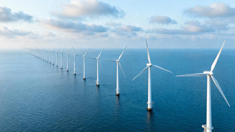
The expansion of offshore wind farms has increased the demand for transmission technologies that can reliably deliver large-scale renewable power to the grid.
This paper reviews recent advances in high-voltage direct current (HVDC) systems, dynamic line rating (DLR), advanced conductors, and energy storage systems (ESS).
Multi-terminal HVDC networks provide controllable, long-distance transmission with reduced curtailment, while DLR improves utilization of existing infrastructure through real-time capacity adjustments.
Advanced conductors such as ACCC increase ampacity, reduce line losses, and enhance wildfire resilience, and ESS technologies stabilize the grid by providing frequency regulation, black start capability, and cost reductions.
Together, these innovations strengthen wind energy transmission and enable a more resilient and sustainable power system.
As the world shifts towards renewable energy driven by climate change and sustainability targets by governments and regulatory bodies, it has increased the demand for efficient transmission of wind energy.
Therefore, over the past three years, there have been significant advancements in wind transmission technologies, such as HVDC transmission systems,
Dynamic Line Rating (DLR), advanced conductors like ACCC, and Energy Storage Systems (ESS). These technologies have substantially improved the efficiency and reliability of wind energy transmission, especially in Offshore Wind Farms (OWFs).
This paper will review these recent innovations, emphasizing their technological benefits and current real-world applications.
Why HVDC for OWFs:
In recent years, developers have built larger OWFs to increase renewable electricity generation, taking advantage of the stronger and more consistent wind conditions found at sea and the flexibility of open ocean space.
However, OWFs are far away from shore, making traditional High Voltage Alternating Current (HVAC) transmission inefficient, as long AC cables face issues like cable skin effects, stability limits, reactive current loss, and require frequency synchronization with the grid [1].
High Voltage Direct Current (HVDC) transmission systems overcome these limitations. In a HVDC transmission system, an offshore converter called a rectifier converts the wind farm’s AC input to DC current, which then passes through the HVDC transmission line and converts back to AC current using the inverter [2].
The comparisons between HVDC and HVAC transmission systems are shown in table 1, using metrics that are limitations in HVAC transmission systems:
HVDC transmission systems eliminate the skin effect and reactive current losses, while offering controllable power flow and asynchronous grid interconnection.
These features make HVDC the most efficient and reliable choice for delivering future large scale offshore wind power over long distances.
Types of HVDC technology:
There are two types of HVDC technologies: Line commutated converter (LCC) and Voltage source converter (VSC) systems.
LCC HVDC transmission systems use thyristor valves (current-controlled switches) that can be arranged in six or twelve pulse bridge configurations to convert AC to DC and back.
Commutation is the transfer of current from one thyristor valve to the next and is driven by the AC system voltage. Key components in a LCC HVDC system include thyristor valve bridges, high harmonic transformers, smoothing reactors, reactive power compensators, and high pass filters [4].
The high harmonic transformer is designed to withstand high AC and DC voltage stress and harmonic currents.
A smoothing reactor, typically in the range of 0.1-0.5 H, is installed on the DC side to maintain steady current flow [4]. Additionally, because thyristors inherently consume reactive power, reactive power compensators are required.
These power compensators are often rated at 60% converter capacity to balance the reactive power demand [4]. Finally, high pass filters are used to suppress switching and harmonic currents to ensure power quality [4].
Figure 2: LCC HVDC Transmission System Process [4].
Because LCCs draw reactive power and depend on a strong AC grid for commutation, they require external reactive compensations like capacitor banks or synchronous condensers.
They have high power and voltage ratings, however, have limited flexibility at low loading and cannot black start weak grids.
VSC transmission systems use self-commutating, voltage-controlled switches called insulated-gate bipolar transistors (IGBT) which enable conversion between AC and DC. The IGBT valve modules, operating with pulse width modulation (PWM), allow for a fully controlled AC voltage.
In addition, a harmonic filter is included, which serves the same role as in a LCC system, but requiring a much smaller and more cost-effective design.
Despite LCC HVDC transmission systems being able to deliver large power transfers with high efficiency, there are some constraints of LCC systems compared to VSC systems. Metric comparing VSC HVDC and LCC HVDC systems are shown in table 2:
In the context of offshore wind farm integration, VSC HVDC transmission system has emerged as the preferred transmission technology because its self-commutation IGBTs and high frequency PWM not only enable cost effective long distance links but also fully satisfy grid requirements like black start capabilities, independent voltage/reactive power support and rapid fault ride through and synthetic inertia for remote wind farms.
Moreover, VSC’s converters and voltage source behavior support the creation and implementation of VSC systems in multi terminal networks.
Point to point to multi terminal grids:
There are many configurations to HVDC systems, such as a monopolar link, bipolar link, and back-to-back, but this paper will only review multi terminal configurations.
Multi terminal HVDC (MTDC) systems exceed the basic two terminal point to point (P2P) HVDC concept by interconnecting three or more converter stations on a common DC network. Instead of a single rectifier inverter pair, MDTC networks allow any terminal to inject or extract power that can connect several OWFs and onshore grids across borders [6],[7].
The comparison of MTDC systems and HVDC systems under a simulation of extreme conditions (heatwaves, wildfires, etc) are shown in a table:
While MTDC systems may be more complex than traditional P2P systems, their flexibility and cut in curtailment make them the technology for gathering power from multiple OWFs and delivering to shore.
The flexibility and reduced curtailment help stabilize grids, reduce costs by just adding another terminal to connect more farms, and poses a potential solution as more wind farms are being built.
There have been recent adoptions of MTDC systems including the Shetland HVDC project and the in-development phase of the North Sea Wind Power Hub, shown in figure 3.
The Shetland HVDC project connects the 443 MW Viking Wind Farm to the GB grid via a 260km subsea cable, featuring a three terminal configuration that splits energy flow from Shetland to Spittal and Blackhillock [9].
As a result, the system can transmit power from the offshore Viking Wind Farm, capable of generating 1.8 TWh annually, powering nearly 500,000 homes [10].
In addition, the Shetland HVDC project connection with the Viking Wind Farm would also support 35 permanent roles and contribute £70 million to the local economy [10].
The North Sea Wind Power Hub is an international MTDC project to connect OWFs across multiple countries including Denmark, Netherlands, Germany, and Norway [11].
The projected benefits of this project based on studies indicate that the transmission asset lifecycle costs could be reduced by 30% over a full 180 GW offshore wind roll out compared to radial connections.
Additionally, the project is expected to increase social welfare by €1.0-1.7 billion per year and projected a 4% reduction in CO2 emissions for Europe’s power sector by 2040. [11].
These projects prove that the MDTC technology for wind energy transmission is not only feasible, but also economically advantageous for large scale renewable energy integration.
DLR advantages:
Conventional Static Line Rating (SLR) are determined using conservative, “worst case” weather assumptions (e.g. 40 C ambient, zero wind, high solar loading) [12].
Under SLR, the ampacity (maximum allowable current) is chosen so that, even in the hottest, no wind, high sun conditions, the conductor won’t overheat or sag beyond safe levels. But often actual weather is milder, resulting in SLR underutilizing transmission assets.
Therefore, Dynamic Line Rating (DLR) is introduced as it continuously adjusts a conductor’s allowable current in real time by measuring tension, which reflects the combined effects of conductor heating, sag, wind cooling, ambient temperature, and solar radiation.
Tension based DLR systems can send live ampacity updates, enabling operators to use temporary increases in capacity when weather conditions permit.
Table 4 will compare SLR and DLR systems incorporated in wind energy transmission.
DLR continuously adapts conductor ampacity to actual weather and operating conditions.
By leveraging real time tension measurements, DLR reduces curtailment of wind generation and smooths power flow, valuable for OWFs.
For OWFs, adding new cables or towers may be expensive, so DLR poses an alternative that delivers immediate efficiency and enhances grid stability.
Although DLR technology poses an alternative that advances with wind transmission, there are some concerns on data accuracy, cybersecurity, and communication complexities.
The Electric Reliability Organization (ERO) emphasizes that the reliability of DLR depends on accurate sensor and weather data, and the need for a cyber secure system to maintain real time data integrity [14].
In addition, the ERO mentions that by utilizing DLR systems, it requires secure communication integration infrastructures to have coordination among operators (transmission owners, operators, and reliability coordinators) for real time DLR data to be integrated smoothly into control rooms and reliability frameworks.
Real world adoptions:
There have been recent adoptions of DLR such as AEL/LineVision 2023 collaboration and National Grid/LineVision 2022 collaboration on UK Offshore Wind Integration.
The AEL/LineVision demonstration deployed DLR on five transmission circuits (including a 345 kV line in Indiana and a 69 kV line in Ohio). There has been data from October 2023 -
March 2024 showing the results of the implementation on the 345 kV line [15]:
The National Grid and LineVision 2022 collaboration utilized LineVision sensors on critical double circuits exporting energy from offshore wind sites to England and Wales [16]. The key findings of implementing these sensors include [17]:
By these recent implementations of DLR, it shows that DLR can result in dramatic increases in ampacity resulting in cheaper energy and reducing wind curtailment risk. This signifies that while the DLR field is still growing, the future of DLR in wind energy transmission is crucial.
ACCC advantages:
Conventional Aluminium Conductor Steel Reinforced (ACSR) conductors consist of one or more layers of cold drawn aluminum strands helically wound around a galvanized high steel core.
The steel core gives the high tensile strength, while aluminum strands provide good conductivity.
There have been two other types of conductors called Aluminum Conductor Steel Supported (ACSS) and Aluminum Conductor Composite Core (ACCC) conductors that have better performance compared to ACSR.
ASCC consists of annealed aluminum strands helically wound around a steel core and ACCC consists of a lightweight, hybrid carbon fiber reinforced polymer core and uses annealed trapezoidal aluminum strands.
Table 5 shows the results of the data when ACSR, ACSS, and ACCC conductors are tested:
While ACCC conductors are significantly more expensive than ACSR and ACSS conductors, their minimal sag, reduced tension loss, and lowest 10-year creep strain combine to deliver up to twice the ampacity and achieve far better performance.
This capability enables wind farm operators to increase export capacity without the expense of installing additional cables or towers. By having the ability to run at higher temperatures with minimal sag, it ensures a reliable power delivery, especially for environmental stresses in OWFs.
Real world adoptions:
Adoptions of ACCC have been demonstrated in several major transmission projects, including American Electric Power’s (AEP) 345 kV reconductoring project, Greece’s Peloponnese 400 kV line, and California’s Transmission Plan, which features projects such as Julian Hinds–Mirage.
In AEP’s project, two 120-mile ACSR lines were replaced with ACCC, resulting in doubled capacity (greater ampacity), a 30% reduction in power losses, and $15 million in energy savings [19].
While data from the more recent Greece and California projects is not yet available, ACCC is expected to deliver similar benefits, including higher ampacity, reduced line losses, and enhanced wildfire resilience [19],[20].
These real-world applications highlight how advanced conductors like ACCC can provide a cost-effective and efficient solution for wind energy transmission.
Types of ESS and ESS advantages:
Energy Storage systems (ESS) store energy for later use, balancing supply and demand in power grids.
The integration of energy storage systems is crucial for renewable energy sources like wind power by storing excess energy when generation exceeds demand and releasing energy during shortages to stabilize the grid.
Ullah et al. categories ESS technologies into different sections, including electrochemical (batteries), mechanical (hydro, compressed air, flywheels, supercapacitors), and chemical (hydrogen) storage [21].
The overview of main ESS types and how they operate are shown in Table 6:
There are many benefits of using Energy Storage Systems for wind farms. These benefits include:
With these benefits, ESS technology poses an effective solution for solving wind transmission issues. As ESS technology continues to mature and become more advanced, it will increase the scale potential of offshore wind farms.
Real world adoptions:
There have been adoptions of energy storage systems for wind transmission systems seen by the incorporation of lithium-ion BESS with the Hornsdale Wind Farm in South Australia.
Initially commissioned in 2017 with a capacity of 100 MW / 129MWh, the project was expanded to 150 MW / 194 MWh.
According to the Hornsdale Power Reserve Year 1 Technical and Market Impact Case Study, the battery is capable of injecting 100 MW within 150 ms, providing Fast Frequency Response (FFR) services [26].
In an August 25, 2018, event, the BESS delivered 84 MW almost instantly, preventing under frequency load shedding which could have led to a statewide blackout [26].
Apart from stability benefits, the BESS also delivered significant economic benefits. In the second year with the incorporation of the BESS, the average Regulation Frequency Control Ancillary Services (FCAS) costs reduced from $470/MWh to only $40/MWh, contributing to $116 million in total FCAS savings [27].
These outcomes show that modern energy storage systems are enhancing the stability and efficiency of wind energy transmission.
Figure 4: Regulation Frequency Control Ancillary Services costs with BESS versus without BESS [27].
The transition to renewable energy requires transmission systems that can reliably deliver large scale offshore wind power to the grid.
Recent innovations like MTDC HVDC networks, DLR, advanced conductors like ACCC, and ESS address the technical and economic challenges of wind transmission.
These technologies not only improve efficiency and reliability but also reduce curtailment, enhance grid stability, and lower overall system costs.
As more real-world adoptions continue to emerge, these advancements show a clear path towards building more interconnected, resilient, and sustainable transmission infrastructures capable of supporting the global shift to clean energy.
Dr. Raj Shah, is a Director at Koehler Instrument Company in New York, where he has worked for the last 25 plus years.
He is an elected Fellow by his peers at ASTM, IChemE, ASTM, AOCS, CMI, STLE, AIC, NLGI, INSTMC, Institute of Physics, The Energy Institute and The Royal Society of Chemistry.
An ASTM Eagle award recipient, Dr. Shah recently coedited the bestseller, “Fuels and Lubricants handbook”, details of which are available at ASTM’s Long-awaited Fuels and Lubricants Handbook https://bit.ly/3u2e6GY.
He earned his doctorate in Chemical Engineering from The Pennsylvania State University and is a Fellow from The Chartered Management Institute, London.
Dr. Shah is also a Chartered Scientist with the Science Council, a Chartered Petroleum Engineer with the Energy Institute and a Chartered Engineer with the Engineering council, UK.
Dr. Shah was recently granted the honorific of “Eminent engineer” with Tau beta Pi, the largest engineering society in the USA.
He is on the Advisory board of directors at Farmingdale university (Mechanical Technology), Auburn Univ (Tribology), SUNY, Farmingdale, (Engineering Management) and State university of NY, Stony Brook (Chemical engineering/ Material Science and engineering).
An Adjunct Professor at the State University of New York, Stony Brook, in the Department of Material Science and Chemical Engineering, Raj also has over 725 publications and has been active in the energy industry for over 3 decades. More information on Raj can be found at https://shorturl.at/JDPZN
Mr. Mathew Roshan and Leo Jiang are Chemical and Molecular Engineering Undergraduate Students at Stony Brook University and interns at Koehler Instrument Company, Holtsville, NY
Mr. William Chen has earned his graduate in Chemical Engineering from the State University of New York, Stony Brook, NY and is a member of the senior internship program at Koehler Instrument company in Holtsville
[1] “PSMA Consulting - electrical power system studies - HVDC vs HVAC transmission,” PSMA Consulting - Power System Studies, https://www.psmaconsulting.com/power-system-studies/hvdc/hvdc-vs-hvac-transmission
[2] High voltage direct current electricity – technical information, https://www.nationalgrid.com/sites/default/files/documents/13784-High%20Voltage%20Direct%20Current%20Electricity%20%E2%80%93%20technical%20information.pdf
[3] High voltage direct current transmission, https://cleanenergygrid.org/wp-content/uploads/2014/08/High-Voltage-Direct-Current-Transmission.pdf
[4] Y. A. Sultan, S. S. Kaddah, Z. H. Ali, and A. A. Eladl, “Control Offshore Wind Farm integrated with HVDC system and storage devices-based IOT: A survey,” e-Prime - Advances in Electrical Engineering, Electronics and Energy, vol. 10, p. 100823, Dec. 2024. doi:10.1016/j.prime.2024.100823
[5] “LCC-HVDC vs VSC-HVDC transmission systems,” PSMA Consulting - Power System Studies, https://www.psmaconsulting.com/power-system-studies/hvdc/lcc-hvdc-vs-vsc-hvdc-transmission-systems
[6] P. RODRIGUEZ and K. ROUZBEHI, “Multi-terminal DC Grids: Challenges and prospects - journal of Modern Power Systems and clean energy,” SpringerLink, https://link.springer.com/article/10.1007/s40565-017-0305-0
[7] G. Buigues, V. Valverde, A. Etxegarai, P. Eguía, and E. Torres, “Present and future multiterminal HVDC systems: Current status and forthcoming developments,” RE&PQJ, vol. 15, no. 1, Jan. 2024. doi:10.24084/repqj15.223
[8] Q. Nguyen et al., “Benefits of multi-terminal HVDC under extreme conditions via production cost modeling analyses,” IEEE Open Access Journal of Power and Energy, vol. 11, pp. 117–129, Mar. 2024. doi:10.1109/oajpe.2024.3376734
[9] “World-leading transmission project energised – first in Europe,” SSEN Transmission, https://www.ssen-transmission.co.uk/news/news--views/2024/8/world-leading-transmission-project-energised--first-in-europe/
[10] Shetland’s Viking Wind Farm and subsea cable boosts UK Clean Energy | SSE, https://www.sse.com/news-and-views/2024/08/viking-wind-farm-and-subsea-cable-boosts-uk-clean-energy-from-shetland/
[11] “Concept paper 4: The Benefits,” North Sea Wind Power Hub, https://northseawindpowerhub.eu/knowledge/concept-paper-4-the-benefits
[12] Dynamic Line ratings, https://cleanenergygrid.org/wp-content/uploads/2014/08/Dynamic-Line-Ratings.pdf
[13] “Dynamic Line Ratings Status, Applications and Opportunities: A GET SET White Paper,” EPRI, https://www.epri.com/research/products/000000003002031444
[14] “Revolutionising grid reliability: Promising role of Dynamic Line ratings,” Global Transmission Report, https://globaltransmission.info/revolutionising-grid-reliability-promising-role-of-dynamic-line-ratings/
[15] J. Engel, “A utility tried out dynamic line ratings. how did it go?,” Factor ThisTM, https://www.renewableenergyworld.com/power-grid/transmission/a-utility-tried-out-dynamic-line-ratings-how-did-it-go/#:~:text=The%20mean%2C%20or%20average%2C%20DLR,49%25%20increase%20over%20static).
[16] “How dynamic line ratings accelerate renewable energy integration,” How Dynamic Line Ratings Accelerate Renewable Energy Integration, https://www.linevisioninc.com/news/how-dynamic-line-ratings-accelerate-renewable-energy-integration
[17] “Reducing low carbon generation curtailment with dynamic line ratings on the England and Wales Transmission System,” LineVision, https://www.linevisioninc.com/resources/reducing-low-carbon-generation-curtailment-with-dynamic-line-ratings-on-the-england-and-wales-transmission-system
[18] P. Parvizi, M. Jalilian, and K. D. Dearn, “Evaluating the mechanical and thermal performance of high-temperature low SAG (HTLS) conductors: A Comparative Study of ACCC, ACSS, and ACSR Conductors,” Results in Engineering, vol. 26, p. 104735, Jun. 2025. doi:10.1016/j.rineng.2025.104735
[19] D. Bryant, “Why ACCC® Conductor is shaping the future of EHV Transmission: A global perspective,” Energy Central, https://energycentral.com/o/ctc-global/why-accc%C2%AE-conductor-shaping-future-ehv-transmission-global-perspective
[20] D. Bryant, “Reconductoring for a resilient California Grid: Accelerating upgrades for a clean energy future,” Energy Central, https://energycentral.com/o/ctc-global/reconductoring-resilient-california-grid-accelerating-upgrades-clean-energy
[21] F. Ullah et al., “A comprehensive review of wind power integration and energy storage technologies for modern grid frequency regulation,” Heliyon, vol. 10, no. 9, May 2024. doi:10.1016/j.heliyon.2024.e30466
[22] V. Amarapala, A. S. Darwish, and P. Farrell, “Storage of wind power energy: Main facts and feasibility − hydrogen as an option,” Renewable Energy and Environmental Sustainability, vol. 8, p. 16, Aug. 2023. doi:10.1051/rees/2023013
[23] J. M. Kluger, M. N. Haji, and A. H. Slocum, “The power balancing benefits of wave energy converters in offshore wind-wave farms with energy storage,” Applied Energy, vol. 331, p. 120389, Feb. 2023. doi:10.1016/j.apenergy.2022.120389
[24] H. Chen et al., “Joint planning of offshore wind power storage and transmission considering carbon emission reduction benefits,” Energies, vol. 15, no. 20, p. 7599, Oct. 2022. doi:10.3390/en15207599
[25] D. Pagnani, Ł. Kocewiak, J. Hjerrild, F. Blaabjerg, and C. L. Bak, “Integrating black start capabilities into offshore wind farms by grid‐forming batteries,” IET Renewable Power Generation, vol. 17, no. 14, pp. 3523–3535, Jan. 2023. doi:10.1049/rpg2.12667
[26] Hornsdale Power Reserve Year 1 Technical and Market Impact Case Study , https://www.aurecongroup.com/-/media/files/downloads-library/thought-leadership/aurecon-hornsdale-power-reserve-impact-study-2018.pdf
[27] Hornsdale Power Reserve Year 2 Technical and Market Impact Case Study, https://www.aurecongroup.com/-/media/files/downloads-library/thought-leadership/aurecon-hornsdale-power-reserve-impact-study-2020.pdf
[28] European Transmission System Operators to develop North Sea Wind Power Hub. (2017, March 9). State of Green. https://stateofgreen.com/en/news/european-transmission-system-operators-to-develop-north-sea-wind-power-hub/
PIN 27.3 June/July 2026

-(1).jpg)