-
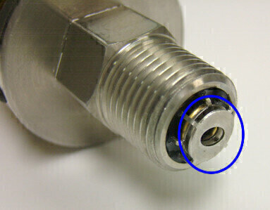 Figure 1: SenGenuity Fluid Condition Sensor (Beta Version) with Parallel Capacitance Cell
 -
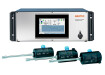
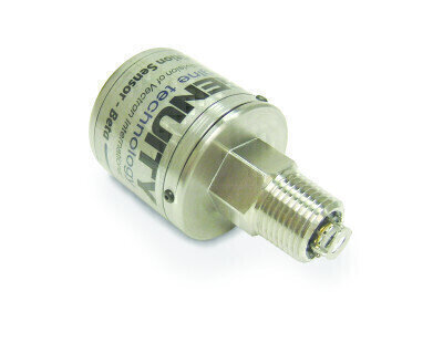 Figure 2: SenGenuity Fluid Condition Sensor (Beta Version) capable of measuring Viscosity, Conductivity and Dielectric Constant
Measurement and Testing
Fluid Condition Sensors for Diesel Engines and High Value Assets
Jan 10 2011
Historically, oil and fluid analysis has taken place in laboratory environments. The wide variety of analytical tests, strengthened by their unmatched accuracy and precision, makes lab based oil analysis an integral part of any serious preventive maintenance program. Today, however, there is a growing demand for on-line, in-line and real-time fluid health monitoring capabilities such as those offered by SenGenuity (USA).
This demand is driven by several factors, including a desire to extend oil-drain intervals for economic and environmental reasons. Secondly by time: although lab testing is relatively accurate, it may not always be timely as there can be delays in sending and testing samples. Delays can also occur if the fluid has to be re-sampled for additional testing to confirm or deny initial test results. The cumulative effects of these delays may make it hard to know the true condition of the oil at a particular point in time. Some companies get around these problems by having test labs located on site but the costs associated with this option puts it beyond the reach of most machine operators. As a result of not taking the true condition of the lubricant into consideration, some operators may replace lubricant prematurely incurring unnecessary costs, or replace it too late thereby risking the overall health of equipment.
Further, the reduction of warranty costs by Original Equipment Manufacturers (OEM). By virtue of not knowing the true condition of lubricants, machine operators may inadvertently cause mechanical failure in equipment, which otherwise would have functioned without any issue. When this occurs within the warranty period it is not uncommon for the OEM to bear the cost of repairing or replacing equipment.
And at last, the end user’s quest to gain a competitive advantage by minimizing downtime and the associated opportunity and repair costs, which are at times significant when equipment is located in remote locations or is hard to reach (e.g. windmills and cranes).
Fluid condition sensors, which provide the ability to continuously monitor the health of lubricants address the need for extended oil-drain intervals, reduce OEM warranty costs and improve the overall equipment availability for the end user. Fluid condition sensors cannot replace lab based oil analysis. Rather, they provide a means to more judiciously make use of detailed lab analysis only when further investigation of lubricant health is warranted.
A fluid condition sensor can provide timely information on rapidly deteriorating machine conditions on a continuous, real-time basis, something that lab based analysis cannot provide. By using such sensors to complement and augment lab based lubricant analysis programs, the end user can improve efficiency, prevent damage and lower costs.
SenGenuity Fluid Condition Sensor Technology
Oil samples have a wide variety of properties measured by a wide variety of tests to determine the condition of the oil. Analytical labs have standardized tests for a wide variety of lubricants depending on their application and use in the field. Typical tests include: viscosity measurements, infrared (IR) spectroscopy to determine the amount of oxidation, nitration and/or sulfation that has occurred, Total Acid Number (TAN) to measure the amount of acidic species present, Total Base Number (TBN) to determine the amount of certain types of additive, soot content, glycol to determine the amount of antifreeze in the oil, amount of fuel in the oil, wear metals, contaminant metals as well as additive metals. Additional tests such as water content, ferrography or particle counts may also be used. An oil or lubricant may fail one or more of these tests.
Recently, papers have been published1,2 demonstrating that it is possible to determine the condition of engine oils by using sensors that measure viscosity, conductivity and dielectric constant. The researchers were able to establish correlations between typical laboratory test results for oils, using tests like those described above, to the viscosity, conductivity and dielectric constant measurements obtained from sensors. The technology to monitor these metrics (viscosity, dielectric constant and conductivity) in-situ either already exists or is actively being developed by companies in the fluid condition sensors arena. The conductivity and dielectric constant of a fluid can be measured by using a parallel plate capacitance cell arrangement, as shown in Figure 1. Measuring the admittance of the cell at a reasonably low excitation frequency ensures that the dielectric loss is negligible. In this case, the conductance of the cell will directly be related to the conductivity of the fluid, while the susceptance of the cell will directly be related to the “static” relative dielectric constant of the fluid.
Viscosity can be measured by placing a piezoelectric thickness shear mode (TSM) resonator (sensing element) in contact with the fluid. The top surface of the sensing element interacts with the fluid forming a thin fluid layer (on the order of microns) that moves with the vibrating surface. The fluid’s viscosity determines the thickness of the fluid layer that is hydro-dynamically coupled to the surface of the resonator. The sensing element resonates in uniform shear motion at frequency ω=2f with an amplitude U. The frequency is known by design and the amplitude is determined by the level of the electrical signal applied to the sensing element. The shear wave penetrates into adjacent fluid to a depth d, determined by the frequency, viscosity and density of the liquid as d=(2/))1/2, where is viscosity, frequency and is density. The shear wave interaction with the fluid changes with changes in viscosity and density, which can be measured by the electrical properties of the piezoelectric sensing element.
No single fluid metric, by itself, is sufficient to provide an accurate assessment of lubricant health. Viscosity, conductivity and dielectric constant by themselves provide only part assessments of fluid condition. However, a combination of some or all of these metrics can provide highly informative signs of overall lubricant health. Changes in fluid condition (i.e. water ingress, soot loading and presence of metal particles) will result in observable changes in the conductivity and dielectric parameters, and when combined with viscosity measurement, can be used as an indicator of overall fluid health. Deterioration in the viscosity of oil can be indicative of fuel dilution, the presence of glycol or additive depletion. Increase in oil viscosity may be indicative of increased soot loading. An increased in soot levels is also expected to increase conductivity and dielectric constant.
Some fluid condition sensors have the capability of tracking all the metrics mentioned above – conductivity, viscosity and dielectric constant – a sign of the progress that has been made since the first fluid condition sensors that relied on only a single metric. However, not all metrics are relevant to every application. For some lubricants, viscosity and dielectric constant can prove to be highly relevant. For others, a combination of viscosity, conductivity and dielectric constant can prove to be ideal. Therefore, there is room to tailor the technology at hand to match sensor capabilities to application requirements and thereby achieve cost savings.
Target Applications
While there are many applications where fluid condition sensors can prove invaluable, the following three areas represent those that would appear to benefit the most are large diesel engines, windmill gearboxes and hydraulic systems.
Capital intensive diesel engines are often used to provide power (either as prime-movers or as electric power generators) for mission critical applications where machine downtime and the potential for any damage caused to the engine need to be prevented to the maximum possible extent. This often results in non-optimal oil drain intervals where the oil changes may be premature to ensure minimal probability of mechanical failure. Fluid condition sensors indicate the need for an oil change or the need for lab-based analysis based on the true condition of the oil. Furthermore, these sensors prove invaluable in detecting the onset or early warning signs of catastrophic failure.
Access to windmill components is one of the biggest obstacles to cost effective maintenance. Fluid condition sensors hold the promise of avoiding the costly and labor intensive efforts involved with obtaining samples from windmill gearboxes to ensure that gearbox oil condition will support continued operation. A fluid condition sensor will signal for the need for an oil change or more detailed lab analysis only when it is needed.
Heavy equipment and earthmovers often include hydraulic systems that can greatly benefit from fluid condition sensors, which can detect rapidly deteriorating fluid condition and the onset of catastrophic events.
Conclusions
As has been established, there is a significant demand to monitor overall lubricant health on a real-time basis. Fluid condition sensors, which can track a variety of fluid condition metrics, including viscosity, conductivity and dielectric constant, provide the continuous monitoring capability required to ensure the uninterrupted operation of capital intensive and mission critical equipment.
References:
1. I.C. Haladay and E.W. Schneider, In-Situ Monitoring of Engine Oils Through Electrical AC Impedance Measurements, SAE-2007-01-4092, SAE International, Warrendale, Pa, 2007
2. I.C. Haladay and E.W. Schneider, Robust On-Board Engine Oil Monitoring. 2. Determination of Initial Oil Quality and Oil Aeration from Electrical Resistivity and Permittivity, SAE-2009-01-2687, SAE International, Warrendale, Pa, 2007
3. www.wikipedia.org, 2010
4. http://physics.info/viscosity, 2010

Digital Edition
PIN 25.1 Feb/March
March 2024
In This Edition Safety - The technology behind the ION Science Tiger XT - Safety with ammonia and LOHCs as hydrogen carriers Analytical Instrumentation - Discussion on new tribology te...
View all digital editions


Events
Apr 28 2024 Montreal, Quebec, Canada
Apr 30 2024 Birmingham, UK
May 03 2024 Seoul, South Korea
May 05 2024 Seville, Spain
May 06 2024 Riyadh, Saudi Arabia