Analytical instrumentation
Published over 13 years ago. See the latest and most current information on Analytical instrumentation.
Nowadays, X-ray fluorescence spectrometry (XRF) is a well-established analytical technique for qualitative and quantitative elemental analysis (sometimes from Be to U) of a wide variety of samples. In particular, the truly multi-element character, acceptable speed and economy, ease of automation and the possibility to directly analyse solid samples are the most important features among the many that have made it a very mature analytical tool for routine quality controls in many industries, as well as for analytical support for the research laboratory. The recent technological advances, including the design of low-power micro-focus tubes and the novel X-ray optics and detectors have made it possible to extend XRF to the determination of low-Z elements and to obtain 2D or 3D information on a micrometre-scale. Furthermore, the recent development and commercialisation of benchtop and portable instrumentation, that offer extreme simplicity of operation in a low-cost design, have promoted even more the approach of XRF for many analytical problems. This article highlights this state-of-the art technique with regards to currently available XRF instrumentation on the market as well as recent applications in environmental and industrial fields.
Basic Principles of XRF
The basic principle of the XRF technique is based on the use of some excitation radiation (usually an X-ray beam) to produce ionisation in the inner shells of the atoms present in the sample due to photoelectric absorption. In the specific case of X-ray radiation, associated wavelengths are in the range from 0.01 to 10 nm, which corresponds to energies in the range from 0.125 to 125 keV. To achieve X-ray production from a given element, the only requirement is to use an excitation radiation with its energy larger than the absorption edge for the corresponding group of lines. Most commercially available X-ray spectrometers have a range from about 0.4 to 20 Å (40 to 0.6 keV), and this range allows measurement of the K series from F (Z=9) to Lu (Z=71), and the L lines from Mn (Z=25) to U (Z=92).
As far as the characteristic emission corresponds to transitions ruled by quantum mechanics principles, the method constitutes a unique technique for the identification of the atoms present in the sample (“qualitative analysis”).” Quantitative” XRF analysis involves the conversion of the net analytical signal (corrected for background and line overlap) to the concentration of analytes by the calibration curve method, obtained with many standard samples. Ideally, the intensity of an analytical line is proportional to the concentration of the analyte in the sample. However, this relationship is not linear in the more general case, since it depends on physical and chemical matrix effects. Therefore, the contribution of matrix effects has to be taken into account in the expression of the emitted radiation intensity to obtain quantitative results. Several methods have been described for matrix effects correction and, in general, they are available in most commercial XRF spectrometers’ software.
Basic components of XRF spectrometers and instrument configurations
Taking into account the fundamental principles of X-rays aforementioned, the basics components of any XRF spectrometer are:
• an excitation source to produce ionisation of the atoms present in the sample due to photoelectric absorption
• a specimen presentation system
• a detection system to collect the characteristic radiation emerging from the sample
• a data collection and signal processing system
Moreover, some XRF systems are also equipped with source or detector modifier devices in order to improve the analytical performance for specific applications.
Usually, XRF spectrometers are divided into two main categories depending on the fundamentals of the detection system: wavelength-dispersive detection systems (WDXRF) and energy-dispersive systems (EDXRF). WDXRF employs diffraction by a dispersing system to physically separate the characteristic wavelengths emitted from the sample. The geometric arrangement of the components in a WDXRF instrument is shown in Figure 1. The X-ray source irradiates the sample and a portion of the characteristic fluorescent radiation from the specimen in passed via a collimator onto the surface of the diffraction device (analysing crystal or multilayer), where individual wavelengths are diffracted to the detector according to Bragg’s law. A goniometer is used to maintain the required angle between the diffraction device and the detector. Owing to the high resolution power of crystals and multi-layered structures, photons corresponding to characteristic lines with close energies can be detected without interfering with each other, thus providing a high specificity in the analysis. As spectral interferences are avoided, the detection can be performed using proportional counter detectors with large efficiency.
Unlike the WDXRF systems, EDXRF spectrometers consist of only two basic units: the excitation source and the detection system. For the EDXRF case, as the resolution of the energy dispersive system is equated directly to the resolution of the detector, typically a semiconductor detector of high intrinsic resolution is employed. The use of this type of detector in combination with a multichannel analyser allows the determination of all of the X-rays emitted by the sample at the same time, giving greater speed in the acquisition and display of data. In practice, however, there is a limit to the maximum count rate that the semiconductor detector can handle. For this reason, usually source modifiers such as filters are placed between the X-ray source and the sample to reduce the continuum of the X-ray tube and thereby avoiding saturating the detector. Another option is the introduction of a pure element or compound target between the primary source and the sample in such a way that a selectable energy range of secondary photons is incident upon the sample. This allows for selective excitation of certain portions of the energy range. In current commercial instruments, using secondary excitation, the primary, the secondary and the characteristic radiation from the sample are configured at mutually orthogonal angles (polarised-EDXRF systems, P-EDXRF). The main advantage of this 3D geometry is that scattered tube radiation cannot reach the detector because of polarisation and thus the sensitivity is improved compared to 2D systems.
The selection of the most suitable configuration is based on the requirements for a given purpose. For instance, EDXRF systems are preferred if multi-element information is needed and WDXRF is usually selected if a fast accurate determination of only a few elements is required but where flexibility is of little importance.
Another variation of EDXRF systems is total reflection X-ray spectrometry (TXRF). In these systems, the primary beam strikes the sample at a glancing angle of less than 0.1º (and not at the typical EDXRF angle of about 40º) and this results in a low penetration depth. Moreover, owing to the grazing incident excitation angle, the detector can be positioned very close to the sample leading to a large solid angle for the detection of the fluorescence signal. This also contributes to an improvement in the sensitivity of TXRF systems compared to conventional EDXRF spectrometers. TXRF is a well-established analytical technique for multi element determination in various sample types, especially liquids and micro samples. To perform analysis under total-reflection conditions, samples must be provided as thin films. For liquid samples, this is done by depositing 5-50 μL of sample on a reflective carrier with a subsequent drying of the drop.
Recent Advances in XRF Instrumentation
During the last decade, noticeable developments have been made in the instrumental aspects of X-ray spectrometry. This progress includes, for instance, considerable improvements in the design and production of detectors and X-ray optics. All this has resulted in a wide variety of instrumentation available today since the first modern commercial WD X-ray spectrometer was introduced in the market at the end of the 1940s.
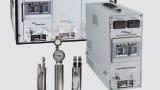
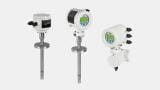
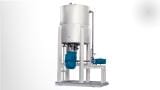
During the last decades, most XRF analyses were performed using large-scale instruments equipped with high-power X-ray tubes (demanding water-cooling systems) and liquid-nitrogen cooled ED detectors. Moreover, these kinds of X-ray spectrometers were often not available to the general user’s community and their use in the field of elemental analysis was limited. Recent technological advances have, however, led to the availability of compact, low-power, metal-ceramic X-ray tubes that can be air cooled (see Figure 2). Despite the fact that low-power X-ray tubes (50W) present a lower sensitivity compared to high-power X-ray tubes (1-4kW), the use of source modifiers (usually primary filters) and the new generation of compact-sized solid-sate detectors (PIN diodes and silicon drift detectors, SDD), based on thermo electrical cooling, have improved the signal-to-noise ratio and now, the instrumental limits of detection of portable and handheld XRF are comparable to those of laboratory-based instruments but at a relatively modest cost investment. Today, almost all manufacturers of XRF spectrometers worldwide provide EDXRF benchtop spectrometers and handheld units at a reasonable price. In Table 1, a summary of benchtop and handheld XRF spectrometers currently available on the market is presented. It is important to remark, that in Table 1, only instruments used for chemical analysis are considered. Even in the case of the more sophisticated XRF configurations (P-EDXRF, WDXRF and TXRF), one can find benchtop prototypes. In Figure 3, a graphical view of some of these XRF systems is displayed.
On the other hand, capillary optics presents also one of the fastest growing X-ray optical technologies because of their capacity to generate high-flux-density beams at the micrometre and sub-micrometre scale. The main particularity of micro-XRF (μ-XRF) instrumentation compared to conventional XRF systems is in the possibility to obtain information on spatial element distribution of the sample at the micrometre scale. In this sense, some of the benchtop EDXRF equipments currently available on the market (i.e., Fischerscope sytems, Fischer, Ltd) give the opportunity to perform measurements using a small spot beam (0.2, 0.6, 1.0 and 2.0mm) similar to large scale μ-XRF instrumentation.
Application of XRF in the Environmental and Industrial Field
Since their development, X-ray methods have been used widely for the determination of major, minor and trace elements in an extensive range of samples in different fields and the use of XRF increases in importance from year to year, as it is highlighted in Figure 4. This fact is mostly due to the technological advances aforementioned as well as the development of new sample preparation strategies. In Table 2 a summary of the analytical characteristics and some current applications for different XRF configurations are displayed.
Conventional EDXRF and WDXRF systems are mostly applied for the analysis of solid samples difficult to be dissolved and analysed by other analytical techniques such as atomic spectroscopy. Using XRF, solid powders can be prepared as pressed pellets, decreasing the use of chemicals and time in sample preparation. Nevertheless, the development of new preconcentration procedures in combination with EDXRF and WDXRF systems has expanded the analytical capabilities of this technique also for the analysis of liquid samples.
In the field of solid sample analysis, the increasing use of handheld EDXRF units is relevant. These devices allow almost point-and-shoot ease of use and can offer results comparable to those of laboratory-based instrument. For this reason, the application of portable systems has found special use in art and archaeology studies owing to the possibility of analysing objects in situ that cannot be brought in the laboratory. Another interesting field of application is in the analysis of environmental samples such as soils (see Figure 5). In this sense, the US-EPA also issued a Standard Operation Procedure for elemental analysis of meals in soils and sediments using a portable EDXRF analyser (EPA Method 6200).
TXRF and μ-XRF techniques are also widely used but for more specific applications. For instance, the main uses of TXRF are related to the chemical analysis of micro-samples or to surface and near-surface analysis in the semiconductor industry. With regards to μ-XRF systems, they are increasingly used in the field of environmental analysis in order to get information of spatial element distribution at the micrometre scale. An example of that fact is shown in Figure 6.
Summary
Nowadays, XRF is a well established analytical technique for elemental analysis of a wide variety of samples. In particular, the multi-element character, the possibility to perform the analysis directly on solid samples, the possibility to perform qualitative, semi-quantitative and quantitative determinations, the wide dynamic range, acceptable speed and economy, easy of automation and versatility are the most important features among the many that have made it a very attractive analytical tool for both routine quality control in many industries, as well as analytical support for the research laboratory. The recent development and commercialization of benchtop/table-top spectrometers, which offer extreme simplicity of operation in a low-cost compact design, have promoted even more the approach of such techniques in the environmental field for many analytical problems.
Despite the fact that XRF technique is mostly used for the analysis of solid samples, the development and application of new sample treatment/preconcentration procedures in combination with XRF systems can expand the applications of this technique in the future.
It is expected that future improvements in instrumentation could increase, even more, the analytical sensitivity and spatial resolution and thus, XRF spectrometry could offer new possibilities in many fields in upcoming years. This instrumental progress includes the development of better designs for excitation-detection, new configurations and also advances in X-ray optics.
References
• E.Marguí, R.Van Grieken. X-Ray Fluorescence Spectrometry and Related Techniques:
An Introduction. Momentum Press, LCC, New York, 2013.
• E.Marguí, R.Van Grieken, C.Fontàs, M.Hidalgo, I.Queralt. Preconcentration methods for the
analysis of liquid samples by X-ray spectrometric techniques. Applied Spectroscopy Reviews 45
(2010) 179-205.
• E.Marguí, I.Queralt, R.Van Grieken. Sample preparation for X-ray fluorescence analysis, in
Encyclopedia of Analytical Chemistry (EAC), edited by R.A. Meyers. John Willey & Sons
(www.wileyeurope.com).
• EPA Method 6200: Field portable X-ray fluorescence spectrometry for the determination of
elemental concentrations in soil and sediment. February, 2007.
• European X-ray Spectrometry Association (www.exsa.hu)
PIN 27.3 June/July 2026