Air Monitoring
Biogas batch fermentation system for laboratory use with automatic gas analysis in real time
Mar 04 2024
Author: Prof. Dr. Gerhard Wiegleb and Dr.-Ing. Joachim Ritter on behalf of WITec GmbH
Free to read
Articles are free to download. Unlock the article to be shown more content, graphs and images.
Biogas is a renewable energy source that is obtained through the fermentation of organic materials. A common system for optimizing the biogas process is the so-called batch fermentation system. In this report, we will take a closer look at the RITTER biogas batch fermentation system and explain how it works and its advantages.
Introduction
The biogas batch fermentation system is a type of anaerobic reactor used to produce biogas. It consists of a closed container with a stirrer called a digester or fermenter.
The fermentation process begins with the addition of organic materials to the digester. This can be various types of biomasses, such as animal excrement, plant residues, food waste or energy crops such as maize or grass. The organic material is added to the digester together with water to create optimal conditions for the anaerobic bacterial culture that carries out the fermentation process.
After the organic material has been placed in the fermenter, the container is sealed airtight to ensure that no oxygen is added. This is important as the fermentation process takes place under anaerobic conditions, where the bacteria break down the organic matter and produce biogas. During the fermentation process, the fermenter is kept at a constant temperature that is suitable for the activity of the bacteria, usually between 35 and 40 degrees Celsius.
The fermentation process itself consists of several successive stages. First comes hydrolysis, in which complex organic molecules are broken down into simpler compounds. This is followed by acidogenesis, in which the products of hydrolysis are converted into organic acids. In the third stage, acetogenesis, the organic acids are converted into acetic acid. Finally, in methanogenesis, acetic acid is converted into methane, which forms the main component of the biogas.
The fermentation process in the biogas batch fermentation system usually takes several days to weeks, depending on the type of biomass used and the specific conditions in the fermenter.
The entire biogas batch fermentation system consists of 3 parts:
1. Fermentation vessels (biogas fermenter)
2. Gas analysis (CH4 and CO2)
3. Flow measurement
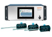
Fig. 1 shows the schematic structure of the entire device.
Fermentation vessels
The fermentation vessel is made of PMMA (polymethyl methacrylate) and is equipped with a gas-tight stirrer. A permanently gas-tight shaft feed-through is always a challenge for gas measurements. Even O-rings or lip seals fail in the long term with aggressive gas components or the smallest particles in the gas flow. In stirrers for fermentation bottles, unsatisfactory compromises are therefore made due to inefficient stirrer rods and/or the smallest gaps on the stirrer shaft. For this reason, RITTER uses a technically sophisticated magnetic coupling between the stirrer motor and stirrer blade. This not only ensures a permanently gas-tight transmission, but also enables the use of individually manufactured stirrer blades adapted to the fermentation substrate.
Special features
• Absolutely gas-tight thanks to magnetic coupling between stirrer motor and stirrer blade
• Various sizes: 0.5 / 1 / 2 liters
• High break resistance due to PMMA construction (without fragile glass gas outlet nozzle)
• Application-specific stirrer blades available
• Stirring speed adjustable via the software from 1 to 30 rpm
• Interval stirring adjustable via the software
• Suitable for media with low and high viscosity
(≤ 450 mm²/sec)
• Gas outlet connection: PVDF tube fitting for tube Ø 4/6 mm
Gas analysis
Methane and carbon dioxide gas concentrations are measured using the tried and tested INFRA.sens modules. As the concentrations can reach values of over 50 % by volume, the respective measuring ranges have been designed for the range from 0 to 100 % by volume. Both gas concentrations cx (CO2) and cx (CH4) are determined using the NDIR method. This method is based on the selective absorption of infrared radiation by the different gas molecules. The CO2 measurement therefore takes place at 4.3µm and the CH4 measurement at 3.4µm. Spectral overlaps are excluded using narrow-band interference filters, so that this type of gas measurement guarantees high selectivity (Wiegleb 2022). The INFRA.sens® uses a multi-channel detector with which both gases can be detected simultaneously in just one sample cell. This has the advantage that both gas concentrations are measured at the same time. If gas sensors were connected in series, there would inevitably be a time offset, which would cause a considerable error, especially at low gas flow rates.
The INFRA.sens® has a very high measuring accuracy of 1%. To achieve this, all measuring errors are compensated electronically. These are in particular:
• Temperature compensation between 5°C and 45°C
• Air pressure compensation between 600hPa and 1200hPa
• Carrier gas dependency between cx (CO2) and cx (CH4)
• High long-term stability with a reference measurement
By using a gold-plated analysis cell, changes in the reflection properties can also be effectively prevented so that the long-term stability can be significantly improved. The INFRA.sens® gas sensor is shown in Fig. 2.
Fig. 2: INFRA.sens® gas measurement module for the simultaneous analysis of methane (CH4) and carbon dioxide (CO2) in an internally gold-plated sample cell (AK30mm)
The measured temperature and pressure values required for compensation are recorded directly in the analysis cell using a microsensor. This provides the exact physical data of the gas to be measured and improves the quality of the electronic compensation.
Data communication takes place via an RS232 interface. A USB interface, a CAN interface and a Modbus protocol are also available. The module is supplied via a 24DC connection, and the electrical power consumption is P<2Watt.
Fig. 3: Array of 9 INFRA.sens® gas measurement modules for measuring the CO2 and CH4 gas concentrations in the respective fermentation vessels with internal tubing (Viton®)
Flow measurement
The MilliGascounter was specially developed to measure very small gas volumes (Scherer 1990). The gas flows into a chamber filled with sealing liquid. A tilting container is arranged in this chamber, in which the gas volume ∆V (≈3mL) collects in the upper part. The displacement of the sealing liquid creates a buoyancy force, causing the container to tilt to the other side. The previously accumulated gas volume is released and can escape via the outlet. This tilting process directs the gas supply into the other chamber so that it now fills with the gas. In this position, too, the displacement of the sealing liquid creates a buoyancy force and the container now tilts back to the starting position. The process is repeated in a certain time interval ∆t, depending on the volume flow. The number n of tilting movements is recorded and multiplied by the volume ∆V ejected per tilting process. This conversion then gives the total volume Vtotal = n-∆V or the volume flow by converting to the time ∆t: [1]
A typical measuring range is 1 to 1000 mL/h, with calibration taking place at 500 mL/h. An accuracy of +/-3% is specified for the MilliGascounter. The accuracy can be further improved by using special evaluation software that automatically corrects the dynamic (volume flow-dependent) error. The algorithm converts the measured values at the current volume flow into the true volume based on the calibration curve. The remaining residual error is then less than +/-1% over the entire measuring range.
Fig. 4: MilliGascounter for detecting low gas flows according to Scherer
Biogas batch fermentation system
The great advantage of the RITTER biogas batch fermentation system is that the fermentation vessels are tempered on all sides in the heating oven. In contrast to the temperature control of the fermentation vessels in a water bath, this prevents uncontrolled cooling of the upper part of the bottle due to ambient air and air currents.
Furthermore, the fermentation vessels can be easily removed from the top of the heating oven for brief visual inspections, even during fermentation. Three different stirring blades are available to achieve optimum adaptation to the viscosity of the fermentation substrate.
With the maximum of 18 fermentation vessels, 3 blank samples, 3 cellulose samples and 4 different fermentation substrates can be tested simultaneously as triplets.
The software supplied enables:
• Recording and standardization of volume and volume flow of up to 18 MilliGascounters in real time
• Data storage in the PC and on an SD card in the interface module for data recovery in the event of a power failure
• Control of the stirrers (speed, interval mode)
• Setting the temperature of the heating oven (thermostat)
• The rack made of aluminum profiles and stainless-steel shelves offers space for up to 18 MilliGascounters and up to 18 optional CO2 absorption bottles.
Fig. 6: Production rate P(t) as a function of fermentation time for different substrates (Scherer et al. 2021)
The production rate P(t) of methane then results from the gas analysis (c concentration) and the volume flow:
The total amount of CH4 (volume VCH4) produced per batch is obtained by integration over the time t:
Summary
The described biogas batch fermentation system is ideally suited for use under laboratory and pilot plant conditions. By using fast-indicating gas sensors (INFRA.sens®) with a low dead volume, the current gas concentration values (CH4 and CO2) can be recorded reliably and without a significant delay. In conjunction with the described flow measurement, the exact production rate P(t) is obtained as a function of time t during the entire test run.
The described gas measurement system can also be extended to other components present in the biogas, such as hydrogen sulfide (H2S), oxygen (O2), ammonia (NH3), water vapor (H2O), etc.
Literature
Wiegleb, G.: Gas Measurement Technology in Theory and Practice, Springer Verlag Wiesbaden 2023 (https://doi.org/10.1007/978-3-658-37232-3)
Scherer, P.: Gas measuring device. German Patent DE 4006508 C2 2.3.1990
Thrän, D, Pfeiffer, D.: New approaches to process optimization in biogas plants, Volume 19, Part 3, Biomass energy use Federal Ministry for Economic Affairs and Energy (2015)
Scherer, P. A., Arthur, R., Antonczyk, S.: Accelerated Biomethane Potential assay for straw with artificially flocculated sludge and defined synthetic manure. Bioresource Technology Reports 15 (2021) 100787
Free to read
Articles are free to download. Please login to read this article or create an account.
Digital Edition
PIN 25.1 Feb/March
March 2024
In This Edition Safety - The technology behind the ION Science Tiger XT - Safety with ammonia and LOHCs as hydrogen carriers Analytical Instrumentation - Discussion on new tribology te...
View all digital editions


Events
Apr 28 2024 Montreal, Quebec, Canada
Apr 30 2024 Birmingham, UK
May 03 2024 Seoul, South Korea
May 05 2024 Seville, Spain
May 06 2024 Riyadh, Saudi Arabia