Analytical instrumentation
Published over 5 years ago. See the latest and most current information on Analytical instrumentation.
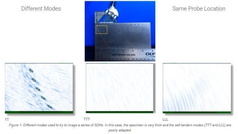
The total focusing method (TFM) has generated a lot of excitement in the nondestructive testing (NDT) field. But there are challenges that had yet to be resolved when using TFM, such as choosing the right mode of propagation (wave set) for a given inspection. Some early adopters of this method quickly realised that using the wrong mode could mean losing an indication from the screen entirely, which came with obvious critical repercussions.
When selecting a mode of propagation (wave set) for a given inspection, the inspector needs to know what kind of defects may occur in the part to be inspected. The type of defect will give some information on the orientation of the reflector, which is critical when inspecting with ultrasonic testing (UT). With conventional UT, phased array UT, or TFM, the basic principle remains the same. The probability of detection (POD) is highest when the transmitted acoustic beam’s angle of incidence is equal to the angle of reflection on the target reflector. Another consideration is the probe parameters. Depending on the probe used, the acoustic waves may not be capable of reaching the targeted defect with appreciable amplitude. Even though the TFM zone is drawn at a particular location, it is possible that the physics will not allow for this specific probe to focus that far into the part. There are so many factors to keep in mind, so how can we simplify and ensure that our inspection is adequate?
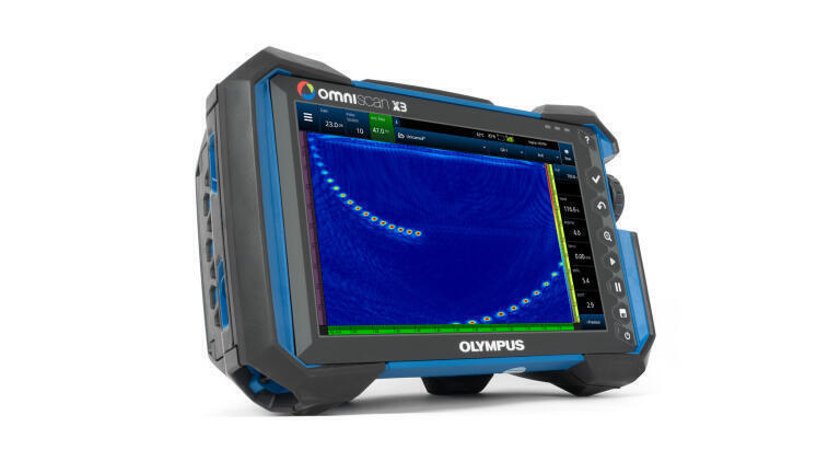
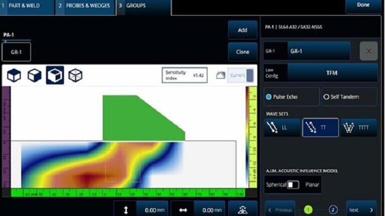
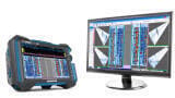
The OmniScan® X3 phased array flaw detector comes with a built-in scan plan tool. Within it is an Acoustic Influence Map (AIM) modeling tool that was specifically designed for TFM inspection. The AIM tool helps users select the right mode of propagation, or wave set, for their inspection.
The AIM modeling tool considers multiple parameters, including the probe and wedge, velocity, thickness, geometry of the specimen, inspection technique, wave sets, and, of course, the parameters entered by the inspector in the “Influence zone” menu to describe the targeted type of defect.
A flaw’s orientation is the principal factor impacting how well a sound beam will be able to detect it. The AIM model clearly demonstrates for the user how good the signal coverage is at a particular angle for a given flaw.
If you are interested in this topic read the whole article here.
PIN 27.3 June/July 2026


-(1).jpg)
2.jpg)
.jpg)


.jpg)