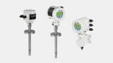
Flow level pressure
Published over 9 years ago. See the latest and most current information on Flow level pressure.
In the previous month’s article, “Who is Manning the Cash Register? Part 1, tank gauging for custody transfer was discussed. If sufficient infrastructure exists, meaning a pipeline is close by, then a line from the production facility can tie into that existing pipeline. This minimizes the potential for disruptions. The tanks can still be gauged as discussed in the previous article, or if sufficient quantity exists to justify the expense of a LACT (Lease Automatic Custody Transfer) unit or an ACT (Automatic Custody Transfer) unit can be installed.
The LACT turns on when the high level switch on the tank is reached by the oil column. The oil is then measured for quantity by the LACT meter and multiple representative samples are captured each time oil is sold by the LACT to be analyzed for quality at the end of the period, i.e. monthly. The LACT unit automatically turns off when the level in the tank reaches the low level switch on the tank. Metering of oil is less labor intensive and minimizes the exposure to contact with the oil and vapors making the process far more efficient and safer. A LACT unit consists of a charge pump, a riser to eliminate in vapors (air eliminator) that may have come out of solution and a sampling system to make sure only merchantable oil goes through the meter. Between the sampling system and the meter a divert valve is installed. If the oil exceeds the allowable sediment and water content, the divert valve changes position and sends the “off spec” oil back to a bad oil tank or some separator for additional conditioning. Here If the oil meets the pipeline specifications the divert valve allows the oil to go through the meter. Downstream of the meter will be at least one thermometer well and pressure gauge. The prover loop portion of the LACT unit makes up the next section of the LACT and allows the prover to be temporarily connected in line so that the volume the meter registers can be compared to the volume the prover registers periodically. Downstream of the prover loop is a back pressure valve that can be adjusted if necessary to control the flow rate through both the meter and the prover. LACT meters are typically the positive displacement type. However, turbines, Coriolis and ultrasonic meters are also found as part of the LACT/ACT unit. The following API standards cover the LACT unit and meters utilized in the industry as well as the prover types that are utilized and the prover operations.
• API MPMS Chapter 4-?Proving Systems Section 1-?Introduction
• API MPMS Chapter 4-?Proving Systems Section 2- Displacement Provers.
• API MPMS Chapter 4-?Proving Systems Section 3- Small Volume Provers.
• API MPMS Chapter 4-?Proving Systems Section 6- Pulse Interpolation.
• API MPMS Chapter 4-?Proving Systems Section 8- Operation of Proving Systems.
• API MPMS Chapter 4-?Proving Systems Section 9-?Methods of Calibration for Displacement and Volumetric Tank Provers Part 1- Introduction to the Determination of the Volume of Displacement and Tank Provers.
• API MPMS Chapter 4-?Proving Systems Section 9-?Methods of Calibration for Displacement and Volumetric Tank Provers Part 2-? Determination of the Volume of Displacement and Tank Provers by the Waterdraw Method of Calibration.
• API MPMS Chapter 5.2 Measurement of Liquid Hydrocarbons by Displacement Meters.
• API MPMS Chapter 5.2 Measurement of Liquid Hydrocarbons by Turbine Meters.
• API MPMS Chapter 5.3 Measurement of Hydrocarbons by Coriolis Meters.
• API MPMS Chapter 5.8 Measurement of Hydrocarbons by Ultrasonic Meters.
• API MPMS Chapter 6-? Metering Assemblies Section 1-?Lease Automatic Custody Transfer (LACT) Systems.
• API MPMS Chapter 6-? Metering Assemblies Section 2-?Loading Rack Metering Systems.
• API MPMS Chapter 6-?Metering Assemblies Section 4-?Metering Systems for Aviation Fueling Facilities.
• API MPMS Chapter 6-?Metering Assemblies Section 5-?Metering Systems for Loading and Unloading.
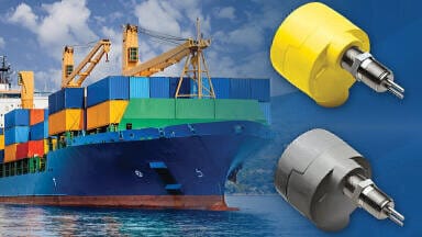
• Marine Bulk Carriers
• API MPMS Chapter 6-?Metering Assemblies Section 6-?Pipeline Metering Systems.
• API MPMS Chapter 6-?Metering Assemblies Section 7-?Metering Viscous Hydrocarbons.
• API MPMS Chapter 8-?Sampling Section 2-?Standard Practice for Automatic Sampling of Liquid Petroleum and Petroleum Products.
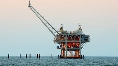
The LACT/ACT meter needs to be tested periodically and compared to a known volume; typically a portable pipe prover or a small volume prover is utilized. The prover can be either portable or stationary for high volume locations or offshore platforms. The meter proving schedule may be based on either time, i.e. typically monthly or on a volume basis. Sun Exploration and Production Company was a partner in the Point Arguello system. The system consisted of three offshore platforms off the coast of California near Santa Barbara. There was also an onshore facility that the oil and gas from the platforms were sent to for additional processing and custody transfer sales into pipelines or tankers. Each platform had its own metering system including a stationary prover as the platforms had different ownerships. All of the locations had an automated proving system which would reprove the meters based on a change in the temperature, pressure or flow rate exceeding an allowable value determined by the measurement committee, since a change in these parameters effect the meter factor.
The quality standards listed as being utilized for tank gauging quality determinations discussed last month may also apply to LACT/ACT unit measurement. However, frequently in pipeline and refinery applications a laboratory method to determine sediment and water may be appropriate as the volumes handled are much larger.
The following laboratory methods may be utilized.
• API MPMS Chapter 9-?Density Determination Section 2-?Standard Test for Density or Relative Density for Light Hydrocarbons by Pressure Hydrometer.
• API MPMS Chapter 10-?Sediment and Water Section 2-?Standard Test Method for Water in Crude Oil by Distillation.
• API MPMS Chapter 10-?Sediment and Water Section3-?Standard Test Method for Water and Sediment in Crude Oil by the Centrifuge Method (Laboratory Procedure).
• API MPMS Chapter 10-?Sediment and Water Section 7- Standard Test Method for Water in Crude Oils by Potentiometric Karl Fischer Titration.
• API MPMS Chapter 10-?Sediment and Water Section 8-?Standard Test Method for Sediment in Crude Oil by Membrane Filtration.
• API MPMS Chapter 10-?Sediment and Water Section 9- Standard Test Method for Water in Crude Oils by Coulemetric Karl Fischer Titration (Note: This method is occasionally used in the field as well).
As you can see this is a lot of information that an employee needs to understand to perform the job properly. The frequency of meter proving is based on volume throughput or set up on a time basis, i.e. monthly. A complete understanding of the metering system and proving operations is necessary to obtain a valid meter factor. He knew he was required to put a bucket under the block and bleed valve, but did not understand the reason. He performed the proving operation and when finished with what he thought was a valid meter factor since the repeatability achieved was adequate; he emptied the half full five gallon bucket of the oil it now contained. He knew he supposed to put a bucket under the block and bleed valve, but did not understand the reason. The leak was consistent and therefore the repeatability was sufficient to obtain a meter factor; however any leakage is unacceptable and invalidates the proving. In order for the proving to be valid every drop of product must go through both the meter and the prover. A leaking block and bleed valve prevents that from occurring, as not all of the oil that went through the meter also went through the prover. Clearly the employee knew what to do but not the reason why it was being done. Both are critical in order to obtain accurate measurement.
Some trucking companies have installed meters on the truck and measure the oil onto the truck via the meter. They take a sample from the line to determine the oil quality. One issue with this method is the harsh environment the meter operates in, since the trucks frequently are travelling along bumpy lease roads to get to the tank to be hauled. The meter factors obtained for stationary meters frequently change and the rough roads just exacerbate that issue, causing frequent repairs or inaccuracies.
Some companies are choosing to utilize multiphase meters measuring the oil, gas and water all at the same time. Multiphase meters have been around for decades and there are various approaches, but they do not provide standard custody transfer quality measurement. However, if both parties agree allowing the less accurate measurement the use of multiphase metering eliminates or at least minimizes a lot of processing of the production fluid into the traditional oil, gas and water streams for accurate measurement and thus reduces the capital and operational cost. Multiphase meters are not capable of accurately measuring a stream that covers 100% oil and 100% gas and everything in between. There are several multiphase meters commercially available and they each have their place. The current multiphase meters all have a range that they are incapable of measuring accurately, some work best in predominately liquids and some in predominately gas applications. If the anticipated fluid range is accurate, the meter selected should work well over the range the meter experiences. Unfortunately, sometimes the anticipated flow is not what is actually received. For example, I was tasked to modify an existing shelf platform to receive the gas from another company’s subsea “gas” well. I designed the modifications to process the gas, accurately measure the gas and then commingle it with the existing platform gas prior to sending it to shore. Unfortunately, the anticipated “gas” well turned out to be an “oil” well, and all of the modifications that were made were now incorrect and to be changed to process and accurately measure the oil. However, as long as the anticipated fluids are actually encountered, multiphase metering is a good solution. Today, companies are even installing subsea multiphase meters as part of offshore platforms. Even though these meters do not achieve custody transfer quality accuracy, it may be well worth it, due to the greatly minimized platform space required and the elimination of the equipment to achieve properly conditioned streams for accurate measurement. Ultimately, it is a business decision. As you have learned, measurement is a complex subject that needs to be fully understood in order to obtain accurate and equitable measurement. Hopefully you and the employees in your company are knowledgeable when it comes to the “cash register” of the company.
If there is any doubt, give me a call and I can provide the training necessary to get everyone proficient in measurement to protect your company’s bottom line.
PIN 27.3 June/July 2026


.jpg)