Measurement and Testing
High-Purity, High-Durability Sampling: Mitigating Corrosion and Maintaining Precision in the Gas Delivery System
Dec 10 2015
Author: Dan Dickerson on behalf of Aura Gas Controls
In the refining and petrochemical industries, recent legislative updates to emissions limits require facilities to precisely monitor fugitive emissions levels while simultaneously calibrating analytical systems with high concentrations of corrosive gasses such as H2S and SO2.
For instance, the US Environmental Protection Agency’s (EPA) Code of Federal Regulations (CFR) Title 40, Part 60, Subpart Ja standard, was set for implementation on November 11, 2015. Once fully enacted, this update holds that facilities must calibrate analytical systems using up to 4% SO2 and 30% H2S, with significantly higher levels being required in certain circumstances [1]. Increasing global scrutiny in combination with initiatives aimed at limiting fugitive emissions from reduced sulphurs and oil/gas production, such as World Bank’s Global Gas Flaring Reduction Partnership, will continue to drive producers and refiners towards higher-purity sampling methods as legislation continues progressing toward lower allowable limits [2].
In meeting current regulations with existing technology, process gas chromatographs (GC) have emerged as a popular analytical technique for measuring flare stack emissions using the total sulphur and hydrogen sulphide methods based on their accuracy with a broad range of chemical components, repeatability, and low total cost of ownership.
Gas chromatographs separate chemical compounds based on identifiable characteristics such as boiling point or molecular size as a heated, conditioned sample passes through a series of columns using a non-targeted gas such as helium, hydrogen, or nitrogen to carry the sample. As the sample enters the columns, compounds separate at different rates and pass across a detector that identifies the analyte species by quantifying the change ratio of a particular variable, such as thermal conductivity, in the presence and absence of the sample.
Enabling this high level of accuracy and repeatability demands that the system utilise a precise calibration system, strictly controlling moisture, and mitigating corrosion in order to protect the operator and the system’s components [3]. This has created a significant challenge for those specifying, fabricating, and operating process analytical systems used in high-purity sampling of active compounds such as H2S and SO2, for the application requires components in the gas delivery system that enable high-precision sampling for low ppm levels, but also high durability for calibration with extremely corrosive and caustic media.
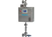
Figure 1 shows a typical configuration for a process GC system. Maintaining reliability and accuracy of the system requires the analyser to be calibrated at the specific process conditions utilised during sample analysis, typically introducing the calibration gas at a minimum of 16.7°C (30°F) above the hydrocarbon’s dew point and at 100-200 kPag (15-30 psig), making pressure, flow, and temperature control essential. To achieve this, National Institute of Standards and Technology (NIST) traceable span and zero gas references are introduced into the system at the specified process conditions, with the outlet pressure from the cylinder being controlled via a two-stage regulator.
Two-stage regulators reduce pressure from the source in two successive phases in order to provide consistent outlet pressure. The regulator’s marginal spring operates in combination with the inlet pressure of the gas to provide closing force to the seat, which is countered by the adjusting spring in the regulator’s bonnet providing opening force that allows gas to flow as the forces balance. The adjusting spring’s opening force is constant; however, as the cylinder empties, the inlet pressure of the gas provides less closing force to the seat. This dynamic causes the outlet pressure to rise as the cylinder empties, typically a 5-7 psig increase per 1000 psig of inlet pressure drop. To achieve consistent outlet pressure, the regulator’s first stage of pressure control reduces the inlet pressure from the cylinder at a preset value usually between 200-400 psig and supplies the second stage. The second stage will reduce the gas down to its final line pressure and maintain it until the cylinder pressure drops below the preset value of the first stage.
Along with precise control of pressure, the two-stage regulator must also maintain the integrity of the calibration gas as it travels through the device. Therefore, it is paramount to utilise two-stage regulators that incorporate metal-to-metal seals in order to avoid sample dilution and harm to the operate and ambient environment. Metal-to-metal seals can achieve 1x10⁻⁹ He ccs leak integrity, eliminating the sample dilution that occurs as air is drawn into the calibration system past the semi-permeable membrane of the elastomeric seals utilised in a standard design. Additionally, when calibrating with high ppm and percent levels of corrosive gasses, metal-to-metal seals eliminate potentially harmful and expensive specialty gas mixtures from escaping to the outside environment by way of the elastomeric seals utilised in a typical design. While stainless steel materials of construction may suffice in certain applications, low ppm sampling systems utilising high concentrations of harmful gasses such as H2S, SO2, NH3, and HCl necessitate the use of superior materials to reduce cycle times and mitigate corrosion.
The traditional method of enabling high-purity, high-durability sampling incorporates system components either constructed of exotic alloys high in nickel content to reduce corrosion, or employing amorphous silicon-based coatings to render the surface of the equipment inert. However, recent technological advances in materials have emerged, providing superior replacements to the existing methods, as carboxysilane materials now simultaneously offer the chemical inertness and corrosive resistance required for low ppm/ppb analysis coupled with percentage level calibrations of active compounds. Figure 2 illustrates the corrosive resistance of carboxysilane materials of construction versus traditional metals and silicon-based surface treatments after a 24 hour, 18% HCl exposure. Carboxysilane materials bond in depth with the crystal lattice of a stainless steel substrate, as the deposition of carbon, oxygen, and silicon achieve a flexible and wear resistant, yet inert surface that provides over two hundred times the corrosion resistance of untreated stainless steel and almost ten times that of amorphous silicon coatings [4].
The application of carbon and oxygen to the substrate increases the hardness of the material, mitigating corrosion from high-percentage concentrations of acid-forming gasses such as H2S and HCl as they react with moisture, along with caustics such as NH3 that form hydroxide as moisture reacts with the active compound. Likewise, the inherent moisture retention exhibited by stainless steel proves problematic, as it is more difficult to dry the system. The carboxysilane’s deposition of silicon is vital to controlling moisture in the sampling system and reducing cycle times, as the material will not absorb moisture or low ppm/ppb mixtures. Relative samples can be registered significantly faster than systems using stainless steel components through the reduction of dry down times and corresponding increase in cycle times. The remaining moisture in the system can also create false analytical results, as compounds being monitored are either absorbed into the moisture and not registered with the sample, or new mixtures can be produced that create an unintended sample composition. Therefore, it is prudent to also incorporate a cross purge device into the calibration gas delivery system in order to reduce the moisture content that can be introduced into the system.
Cross purges enable the user to remove moisture and residual gas left in the delivery system after calibration cycles or replacement of empty cylinders. As the regulator is disconnected from the cylinder valve during change out, moisture is introduced into the equipment through the cylinder connection, which is then forced into the gas delivery system as the calibration gas begins to flow. The resulting acid or hydroxide formed when the moisture reacts with the active compound will begin to degrade system components when in a non-flowing condition. This dynamic can be eliminated by performing a positive displacement purge with an inert gas, such as N2 or Ar. The purge gas is introduced into the system through the purge gas inlet, creating a flow path through the device, and exits either through the purge gas vent or through the regulator if a bleed valve is installed downstream, carrying the corrosion producing gasses and moisture out of the system. Purge-vent preference is determined by the centrally located selector valve, isolating the desired flow path for the purge gas. The other essential feature to an effective cross-purge device is an integral snorkel tube, forcing the purge gas to flow completely through the device and back to the cylinder valve prior to venting.
Conversely, standard designs leave a portion of moisture and calibration gas in the cylinder connection, creating opportunities for corrosion and sample contamination. Figure 3 shows a cross-purge design that incorporates a snorkel tube into the cylinder connection, highlighting how purge gas is introduced, transported, and vented in order to carry excess moisture and calibration gas out of the system. The cross-purge design, in combination with metal-to-metal seal cylinder regulators and carboxysilane materials of construction, can radically mitigate corrosion and moisture in a process GC system, ensuring the highest levels of precision and efficiency available.
In addition to gas chromatography systems used in reduced sulphur analysis, corrosion and moisture play a similar role in affecting the accuracy and repeatability of analytical instrumentation systems across numerous applications. Regardless of the analytical technique and technology, the principles and techniques discussed apply overall to warranting proper function, longevity, and precision of the system.
References
1. Yokogawa Corporation of America, 12530 West Airport Blvd, Sugarland, TX, USA. http://www.yokogawa.com/us/products/process-analyzers/process-analyzer-systems-integration/subpart-ja-compliant-systems.htm#downloads
2. The World Bank, 1818 H. Street NW, Washington, DC, USA. http://www.worldbank.org/en/programs/gasflaringreduction
3. Emerson Process Measurement, 11100 Brittmoore Park Dr, Houston, TX, USA. www.emersonprocess.com
4. Silcotek, 225 Penn Tech Dr, Bellafonte, PA, USA. www.silcotek.com/whitepapers
Digital Edition
PIN 25.1 Feb/March
March 2024
In This Edition Safety - The technology behind the ION Science Tiger XT - Safety with ammonia and LOHCs as hydrogen carriers Analytical Instrumentation - Discussion on new tribology te...
View all digital editions


Events
Apr 22 2024 Hannover, Germany
Apr 22 2024 Marrakech, Morroco
Apr 22 2024 Muscat, Oman
Apr 22 2024 Rotterdam, Netherlands
Apr 23 2024 Singapore